


Tiberio
New Member
Hello.
I bought a Kenwood KA-5500 with a dead channel. Once open, it was clear it stopped working when a cup of thick, sugar dense coffee was spilled on the power amplifier board.

Alcohol does not dissolve sugar so my only option was to wash the board with water, which believe me was the last thing I wanted to do...
Then I noticed someone had previously worked on this unit, and changed just one of the transistors in the left channel differential pair with a different type altogether (the pair at the first stage of the power amp). So all 4 transistors (2 per channel) had to go :-(
Here are the differential "pairs" I have removed.
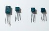
FYI: the service manual says those should be 2SA763 but I am sure the 2SA841 were stock, meaning that substitution was blessed by Kenwood. I have replaced them with KSA992FBU which works just fine.
There was also a BC172 as a replacement for a Japanese 2SA733 in the protection circuit. The BCs have a different pin layout and a shiny metal cap which made it stand out like a sore thumb, I had to get rid of it . It got replaced with a ksa733C and the C matters.
Not sure how to test this protection circuit, I'll post the question separately.

The next problem was that I could not set the bias on this channel. With the Qe8 current source working (I could see 2mA through the resistor Re20 ) , I tried changing Qe10 and YESSSS ! bias started working again. Qe10 was indeed leaking and got replaced by a KSA992F
Since I had the power amp board out of the frame for a shower, I decided to recap it, except for a "nonpolarized cap Ce27" which I would not know how to replace ( I am thinking to use a Nichicon UES Series, Bi-Polar, Radial Leaded Aluminum Electrolytic Capacitors - assuming I can get one of those over here. I will post also this question separately to get some feedback).
As indicated by hopjohn in an old post, the foam on the back of the VU-meters was crumbling in small particles, falling on the tone defeat switch.

... so I also opted for some craft felt as replacement.

Here is the family picture of all that was replaced from the amp board.
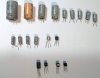
My plan is to compare this unit with my other KA-5700 and see which one wins the top shelf spot ;-)
I hope this post will help someone out there !!! Most of what I know about vintage gears, I have learned it here.
I bought a Kenwood KA-5500 with a dead channel. Once open, it was clear it stopped working when a cup of thick, sugar dense coffee was spilled on the power amplifier board.
Alcohol does not dissolve sugar so my only option was to wash the board with water, which believe me was the last thing I wanted to do...
Then I noticed someone had previously worked on this unit, and changed just one of the transistors in the left channel differential pair with a different type altogether (the pair at the first stage of the power amp). So all 4 transistors (2 per channel) had to go :-(
Here are the differential "pairs" I have removed.
FYI: the service manual says those should be 2SA763 but I am sure the 2SA841 were stock, meaning that substitution was blessed by Kenwood. I have replaced them with KSA992FBU which works just fine.
There was also a BC172 as a replacement for a Japanese 2SA733 in the protection circuit. The BCs have a different pin layout and a shiny metal cap which made it stand out like a sore thumb, I had to get rid of it
. It got replaced with a ksa733C and the C matters.Not sure how to test this protection circuit, I'll post the question separately.
The next problem was that I could not set the bias on this channel. With the Qe8 current source working (I could see 2mA through the resistor Re20 ) , I tried changing Qe10 and YESSSS ! bias started working again. Qe10 was indeed leaking and got replaced by a KSA992F
Since I had the power amp board out of the frame for a shower, I decided to recap it, except for a "nonpolarized cap Ce27" which I would not know how to replace ( I am thinking to use a Nichicon UES Series, Bi-Polar, Radial Leaded Aluminum Electrolytic Capacitors - assuming I can get one of those over here. I will post also this question separately to get some feedback).
As indicated by hopjohn in an old post, the foam on the back of the VU-meters was crumbling in small particles, falling on the tone defeat switch.
... so I also opted for some craft felt as replacement.
Here is the family picture of all that was replaced from the amp board.
My plan is to compare this unit with my other KA-5700 and see which one wins the top shelf spot ;-)
I hope this post will help someone out there !!! Most of what I know about vintage gears, I have learned it here.

