• The move to the new server is done. There are some software and database maintenance updates in process. This has us passing the hat around to help out. We appreciate any donations. Seriously, even a dollar helps. The payment page may be found here - https://www.audiokarma.org/support.html

A little help for a newbie?

Musicmans

New Member
Hello everyone,
I've dipped a toe into trying to repair an amp but I've got stuck and need a little advice.

I fished an NAD 3020 series 20 amp out of a municipal waste tip hoping someone had tossed a perfectly serviceable amp. I got it home, wired it up and sadly it wasn't. Switching on produced a nasty buzzing noise with the music along with a flickering power led. This buzzing is loud with no volume and then is pretty much gone with increased volume. Oh dear.
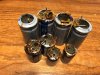
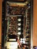
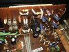
I googled about for solutions and came by forums posts saying things like bad capacitors or even a simple blown fuse could be the problem. So I opened it up and the fuses were good although the power caps had some of looking dark residue at the bottom of them. At this point I felt like I was out of my depth and best get someone with a clue to look it over before I do more damage.
So I took it to a local repair shop and for £20 they told me the board was cracked near the speaker terminal and the caps indeed look bad but after that who knows.
Fearing this free amp was gonna cost alot to repair than it's worth I thought I'd try figuring out myself what's wrong and learn something on the way.

Anyway after patching a couple broken traces and recapping the board I plugged it back in to some scrap-able speakers and... still buzzing and no left channel. Ah crap.
Back to the forum to see if it could be something else, checked over diodes and the bridge rectifier which *i think* are fine I now think the missing left channel is due to a broken terminal connection which seems to have gone after I reflowed the terminals solder but the buzzing is where I'm stuck.

I found posts mentioning that the power switch on these amps can break and cause an arc of AC which I'm guessing is the noise I can hear from the descriptions, the flickering power led seems to be somewhat of an indication of this too but I don't know how to check the switch.

I've checked across the terminals for continuity and all I get is a reading across the two rear terminals regardless of the switch in the ON or OFF position. What should a healthy switch read or do I need to check it another way.
I saw that leesonic replaced his switch with one from Mouser (612-P197SBEE) and recommended a to replace the ceramic caps across it too.

Which type of caps should I use?

Is this switch ok to use instead of the mouser part? And would I need to connect it in a different way to the way the OEM switch is soldered? -
http://www.conrad-electronic.co.uk/...P1TL-6SASHA-latch-1-pcs?queryFromSuggest=true

Any help will be really appreciated!
 

Attachments

  • IMG_6695.JPG
    IMG_6695.JPG
    116.9 KB · Views: 62
  • IMG_6696.JPG
    IMG_6696.JPG
    142.8 KB · Views: 61
  • IMG_6700.JPG
    IMG_6700.JPG
    108.4 KB · Views: 62
  • IMG_6705.JPG
    IMG_6705.JPG
    86 KB · Views: 59
Register to hide this ad
Power supply filter capacitors.

Brown stuff around bases is just glue but hum independent of volume control is almost always filter capacitors in the power supply.

Forget the switch as it's probably ok. Also, the power switch would not be associated with your hum problem.
 
Hello Musicmans, Welcome to AK. If you need the Owners and Service Manuals check HiFi Engine.com. The picture of the caps show 2 PS caps cracked on the bottom. 2 of the other caps show damage to the wrapping (label) of the caps. Also since the amp has a cracked PCB check for broken solder joints with a magnifier. Hope this helps for a start. Good luck. Good people here on AK.
 
From the photos - your 3020 looks like one of the earlier (preferred) models - it's well worth repairing. My first foray into DIY was a very similar 3020 project, albeit maybe not quite as bad - the good news is it's very do-able, and the majority of parts you're likely to need are basically cheaply available. I too treated it very much as a 'do or die' learning project - it was going to get fixed as well as possible, or not at all...... so it ended up being (very) deeply cleaned, heavily 'stripped', recapped, rebuilt, and basically completely serviced, the full 'Leesonic' as it were (with his help I should add !).

Where abouts are you in UK ? and could you maybe give us a bit more idea of your knowledge level ? e.g., do you have / understand the service manual ? read a schematic ? use a DMM to take measurements vs. schematic, etc. ?
 
Thanks for the welcome everyone! I'll try to reply with as much info as much info as I can.

I'd have considered myself a complete novice before I started on this amp, I did design technology at gcse but that was a while back and I've had to revise a lot of info in this last few weeks before I felt confident enough to proceed.
I bought a DMM to check continuity around the broken board area but I'm uncertain exactly how to check things beyond that and measuring diodes (iffy there too). I've seen mention of checking and setting "DC offset" but I'm unsure how and if it's necessary in this case.

Thanks for the advice cademan, The sound I'm hearing has remained after I've replaced all of the capacitors on the main board, it sounds more like an aggressive buzzing at no volume and not a hum like the sort of sounds I've heard at electrical substations. I have also noticed a momentary increase in the buzz as I switch the amp off.

Hi NAD80, I've got a copy of the service manual thanks. I noticed the cracked bungs which got my hopes up that all would be well after I recaped but sadly the buzzing has persisted. I think I solved the problem with the dead left channel by discovering a intermittent connecting at the speaker terminals. I guessed that the solder had been cracked when it was dropped so I reflowed the solder and it seem to have solved that.

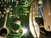
Hello Goldie99, I just checked and the board reads "revision c" and has the "fulet" logo which I believe is an earlier model. There are some numbers there too "19-1095" but I'm unsure what they mean. The serial number is 3208855.
I haven't stripped it further than taking the top and bottom off and I have given it a blow out with an air can and a liberal spraying with contact cleaner. I've not attempted any further cleaning, when you say deep cleaning what would that involve?
I'm near Nottingham and my knowledge level is basically what I've gathered over the last month or so whilst brownsing the forums, I have managed to work out where the schematic relates to the actual circuit board, I was planning to replace the resistors in the signal path with metal film so I studied it to figure out which they were.
My DMM measuring ability is limited to checking continuity and I compared diode readings between the two channels, I've no idea what the readings should be but they all were similar to their opposite channels component so I'm guessing they're ok. I wouldn't know how to use it to check currents or suchlike but I was wondering about trying to check the dc offset to see if that was causing the buzzing.

I hope that gives a clearer picture as to what I've done and how the amps acting.
Thanks again everyone!
 
OK, there's a few things I'd suggest initially - it sounds as though the amp is basically 'working', so I'd suggest to make & use a DBT (dim bulb tester) for any further testing / repairs - until it's fixed basically. It won't necessarily stop you making a mistake, or slippling with a meter probe etc., but it will help minimise any potential further damage if you do. If you search DBT on the forum you'll find plenty of info.

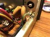
One of the difficulties with 3020's is identifying the correct schematic - yours is probably the first download link on the hifiengine site https://www.hifiengine.com/manual_library/nad/3020.shtml , specifically the first 3 diagrams, but don't be surprised if you find minor differences. A couple of clear 'overall' photos from above / below the amp would help identify it, and see if it's been 'repaired' or modified at all in the past.

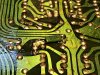
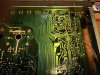
The cracked pcb suggests the amp was dropped at some point (nice repair to the traces by the way), so it would certainly be worth checking for additional dry / damaged solder joints - NAD 3020's are notorious for bad solder joints at the best of times, especially on or near the rear input/output sockets & connections. If you search google images for "dry or damaged solder joints", you'll see plenty of examples of what to look for. The crack in the pcb can be repaired / stabilised with any decent epoxy - I'd just use a small amount of 2 component Araldite and a couple of cocktail sticks to work it into & around the crack (clean carefully in/around the crack first with Acetone if possible - nail polish remover will do - but don't get it everywhere, it will attack many plastics).

Unless the amp is particularly dirty, I probably wouldn't recommend deep cleaning at this point - maybe as you get more practice & have sorted the fault(s), otherwise, you have the possibility of introducing more problems. I'd also advise against changing to metal film resistors at the moment, for the same reason - my focus would be, identify the fault(s), fix the faults, and then move on to any optional changes like recapping, changing resistors, etc.etc.. Others may have different approaches, but that works for me. In the mean time, if you want to read up on amp deep-cleaning, the following thread covers the details: http://www.audiokarma.org/forums/index.php?threads/tutorial-deep-cleaning-an-amplifier.258899/

I assume the 'buzzing' you have is on both channels ? if so, it suggests a fault which is in those parts of the circuit common to both channels, usually one or other of the power supplies - you have basically 2 separate power supplies, one supplying the majority of the amp, and the other just the power amp drivers and outputs. When you say you recapped the board - do you mean you replaced ALL of the electrolytic caps on the main pcb (your photo only shows 8 old caps - there are a lot more) ? also, did you recap the separate power supply pcb, the one mounted vertically at the back of the amp ?

Depending upon the answers, the next step for me would probably be to start measuring a few PS voltages. In the mean time, if you want to check the DC offsets, http://audiokarma.org/forums/index.php?threads/amplifier-distortion-dc-offset-and-you.5634/ is THE reference thread (you only need to read the first few pages). It's not what's causing the buzzing, or even something to adjust at this point, but it's a basic check that I'd use on any unknown amp before connecting loudspeakers, especially good speakers, so probably worth getting used to anyway.

Finally, just a couple of points for the DMM - it's a good idea to tape (or heatshrink) insulate the metal part of the probes, so that only the end ca. 1mm is open..... it's all too easy to slip when measuring, and inadvertantly 'short' something with a meter probe. If only the end 1mm is open, the chances are much better that you'll get away with a slip (you can guess how I know....). 'Mini-grabber' leads are much better & safer, and well worth getting. Also, you should probably avoid ever using the DC ampere ranges on the meter, unless you're absolutely sure you need to & want to...

Anyway - hope some of this helps - as you might have gathered, I quite like the 3020....
 
Thanks for the advice!
I'm going to make a DBT for further testing, thanks for suggesting that.
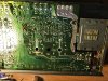
I think I've got one of the earlier versions before the A variation. The schematic is the same as the one I downloaded as far as I can tell, the power caps are near the headphone jack and not in the middle of the board. The only thing I'm unsure of is a couple components that are soldered to the underside of the board.
I'm pretty sure it wasn't touched before I got it, it was very dusty inside and the screws on the cover looked unmarked. I gave it a blow out and sprayed down with contact cleaner and it looks ok in my opinion. I was thinking on rubbing the terminals down as they're quite dull.
I'd not thought about securing the crack, I'll get on that thanks.
I've so far replaced all the electrolytic ladies on the main board and back board, I only took a pic of the larger caps as they looked swollen or grungy. I didn't do the caps on the small led board, I assumed they would likely be serviceable enough for now.
I've not touched the resistors and was gonna leave that till after the buzzing was solved.
The buzzing is both channels, when I tried just using the pre amp the buzzing was still there.
Thanks for the advice on wrapping the DMM probes, I think I'll get a pair of the mini hook type as they look a lot easier to work with.

I have no idea where to start checking voltage/currents to find the source of the buzz so any suggestions would be helpful. My DMM has 4 probe plugs and I'm currently using the black in the COM and the red probe in V/ohm plug. The other two are 10A and mA.
It's model no is M92D by challenge, just a cheapie from Argos

Thanks again for all the help, I've not had chance to work on it these last few days but I can get back at it now.
 

Attachments

  • IMG_6714.JPG
    IMG_6714.JPG
    138.6 KB · Views: 29
  • IMG_6715.JPG
    IMG_6715.JPG
    97 KB · Views: 27
  • IMG_6717.JPG
    IMG_6717.JPG
    160.6 KB · Views: 30
  • IMG_6720.JPG
    IMG_6720.JPG
    81.1 KB · Views: 29
  • IMG_6721.JPG
    IMG_6721.JPG
    123.9 KB · Views: 28
  • IMG_6722.JPG
    IMG_6722.JPG
    70 KB · Views: 28
  • IMG_6728.JPG
    IMG_6728.JPG
    108.8 KB · Views: 28
  • IMG_6729.JPG
    IMG_6729.JPG
    151.3 KB · Views: 27
  • IMG_6731.JPG
    IMG_6731.JPG
    149.8 KB · Views: 28
It is a fairly early version - even down to the dedicated 6V transformer winding supplying the LED power indicator board (the long blue wire going to it). Definitely one to restore.

I don't recognise either of the additions under the pcb, the green one is obviously a small mylar cap, the red one ?, and exactly what they're doing or why, I've no idea - if you can work out where they're connected, or post close up photos showing exactly where they connect to the pcb, someone may be able to clarify. For the time being though, I'd leave them both where they are.

From the damage to the speaker connection terminal block, I'd suggest to have a very close look for further pcb & trace damage (a large illuminated magnifying lamp helps a lot if you have one), and eventually even replace the connection block if it's damaged - Conrad in UK carry them (you have to dismantle & swap the colours a little, but it's simple): http://www.conrad-electronic.co.uk/...r-of-pins-4-Black-BKL-Electronic-205026-1-pcs It would be good if you do have magnification, to go over the whole amp looking for any visual problems (bad solder joints, broken wires, touching component leads, damaged components, etc.). You could double check at the same time that all of the new caps are installed correctly (vis a vis +/- orientation).

You said the buzzing is present on both channels when you use it only as a pre-amp, so with the pre-out / main-in jumpers removed, and presumably another amp connected ? Could you please expand on the details a bit - so, is the buzzing continuous ? the same on all inputs (don't connect anything to the phono inputs except a turntable) ? do you have any inputs connected ? how do the controls affect it (volume, balance, bass, treble, loudness, clipping switch) ? and do you still have the main power on/off LED flickering ? etc.

On the voltage front, if you've never measured a voltage, I'd suggest to start with just the dc-offsets - that can be done without opening the amp, and should be without DBT. Just set the volume to minimum, bass, treble, and balance controls all centred, and select any input with nothing connected to it. No speakers connected at all. Set your meter for the DC 200 millivolts range (200mV DC), put the black probe to either of the black speaker connection terminals, and the red probe to the corresponding red speaker terminal, and turn the amp on. The DMM reading should give the DC-offset in mV for that channel..... it'll change slowly over a few minutes while it settles. Turn the amp off, move the probes to the other 2 speaker terminals, and repeat for the DC-offset of the other channel. With luck you'll have values below ca. 50mV for each channel.

The only real hazard with measuring DC-offset - is to make sure you never have any direct connection between the black / red speaker terminals - that would short your output transistors + more, and is why I suggest connecting the DMM probes with the amp turned off.
 
Sorry that this reply is staggeringly late but rest assured that your advice was very helpful, I just got frustrated and ended up putting the thing in a corner for months until I plucked up the courage to have another go and then completely forgot to post a reply to update how I got on. Again, sorry about that.
Anyway, here a quick roundup of where I ended up.
I (eventually) discovered the culprit for the buzzing was the On/Off switch arching. After taking it apart I found the contacts were black with carbon so a cleaned them and reassembled it only to find the same issue. After further research I came to the opinion that the ceramic capacitors on the switch had gone bad so I took a chance and switched those out with a couple Wima mks4’s and that seemed to do the trick.
I then tried to set the offset but the original variable resistors were less than accurate so I replaced them with some newer units and set the DC offset as close to 0mv as I could which ended up at 0.1 and 0.8.
The unit worked just fine except for being a bit thin on the bass side which I took for its general sound.
After getting over the frustration of the power switch it was rather fun bringing the little thing back to life and I have since tried my hand recapping my phone pre amp and I’m currently fiddling with an old Pioneer amp. Nothings blown up yet so thanks again for all the valuable help!
 
Glad you got it fixed. That on /off switch arcing can be a problem in a lot of gear. Enjoy the music. Good luck with the Pioneer.
 
Yes, good to hear it's working again. Dismantling and cleaning those switches can be 'fun', although it may be a temporary fix (the contact plating gets damaged by arcing / cleaning).
You should however replace the 2X MKS4 caps you used - if they're the ones directly at the power on/off switch, then they should be X-rated safety caps in UK.
 
Back
Top Bottom