• The move to the new server is done. There are some software and database maintenance updates in process. This has us passing the hat around to help out. We appreciate any donations. Seriously, even a dollar helps. The payment page may be found here - https://www.audiokarma.org/support.html

A little help from my friends? Kenwood KA-3500

Frank Wild

New Member
With loads of help from Hopjohn
https://audiokarma.org/forums/index.php?threads/the-ka-3500-restoration.840144/

and Super Noob
https://audiokarma.org/forums/index.php?threads/project-kenwood-ka-3500-nate-dogg.983234/

I’m restoring my dear old Kenwood KA-3500, not my first soldering project (that was a Heathkit guitar amp in 1975) but my first real cap job.

With new capacitors in and the bias set to 40 mv, things appear to be working, but two issues remain:

1 - The DC offset at the speaker terminals is about 107 mv (L) and 137 mv (R).
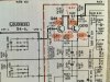
2 - The voltages on this part of the pre-amp (photo) are pretty far off, both left and right channels. In the photo, my red scrawl shows my measured voltages next to the recommended ones. At first, I thought maybe Rd34 had failed, but it hasn’t. Are QD7-10 suspect? Any other suggestions?
 

Attachments

  • IMG_2954.jpg
    IMG_2954.jpg
    130.4 KB · Views: 28
Register to hide this ad
Yes it was, with a 40w bulb. Is that good news? (For what it's worth, the bulb glows then fades when I switch the amp on, as it should. As the amp warms up, the bulb begins to glow VERY dimly.)
 
Ah, too bad! The numbers changed very little with the amp plugged into the mains.
There should be -8.5v at the collector of Q10, for instance, and I've got almost -14v.
Voltages on either side of R34 are both very close to -1.2v. They should be -.6v and -1.5v.
And so on.
 
With loads of help from Hopjohn
https://audiokarma.org/forums/index.php?threads/the-ka-3500-restoration.840144/

and Super Noob
https://audiokarma.org/forums/index.php?threads/project-kenwood-ka-3500-nate-dogg.983234/

I’m restoring my dear old Kenwood KA-3500, not my first soldering project (that was a Heathkit guitar amp in 1975) but my first real cap job.

With new capacitors in and the bias set to 40 mv, things appear to be working, but two issues remain:

1 - The DC offset at the speaker terminals is about 107 mv (L) and 137 mv (R).
2 - The voltages on this part of the pre-amp (photo) are pretty far off, both left and right channels. In the photo, my red scrawl shows my measured voltages next to the recommended ones. At first, I thought maybe Rd34 had failed, but it hasn’t. Are QD7-10 suspect? Any other suggestions?

Frank, you need to change Qd7-10 with closer matched ksa992 transistors to lower DC offset. This is a common problem. there is no pot to adjust DC offset in the KA-3500.

if you don't have any, you might need to buy 20 to find 2 pairs that are close. Mouser or Digikey are good suppliers. You will also need a way to measure Hfe. Or swing by and I'll give you some.
 
I ended up installing some pots into the circuit to dial in the dc offset, then removed those and installed the appropriate sized resistors.
I can't remember where the Hfe was on the transistors, maybe mine weren't matched well?
 
Frank, you need to change Qd7-10 with closer matched ksa992 transistors to lower DC offset. This is a common problem. there is no pot to adjust DC offset in the KA-3500.

if you don't have any, you might need to buy 20 to find 2 pairs that are close. Mouser or Digikey are good suppliers. You will also need a way to measure Hfe. Or swing by and I'll give you some.

From a Minnesotan in exile, thanks for this! I had twenty KSA992 in my Mouser cart already. I changed it to 30 instead and placed the order. Should I match Q7 with Q8 (left and right) or should I match Q7 with Q10? If this brings the DC offset down to a better level, will those voltages around the transistors be closer to the mark too? I saw "hfe" on my meter yesterday and made a mental note to find out what it's for. Done!
 
Q8 and Q10 should be matched. I cannot see the other diff pair from the schematic above. Q7-Q9?

with modern manufacturing, the tolerance might be close enough with your first 4 transistors you pull. I don't recall how close they need to be. I have a tape of 992 with measured Hfe on the paper.
 
Last edited:
Frank, the voltages that you measured on post #1 are good, considering variations from one transistor to another. The schematic is in error on two points: it's not possible to have -1.5V at the emitter of Qd10, and -3.2V at its base (the difference should be of the order of 0.6V), and it's not possible to have 0.9V drop in Rd34. If there was 0.9V drop in Rd34, transistor Qd8 would be in total saturation.

For the offset, you didn't say but I am sure that your offset is negative (approximately -120mV or so). The transistors that should be matched are Qe1-Qe3 (L channel) and Qe2-Qe4 (R channel). Even so, you will not have 0 offset. You will need to replace Re9 (and Re10) by lower resistors. 820 Ohm would be probably perfect.

There is absolutely no relation between the output offset voltage (at the speaker terminals) and Qd7, Qd8, Qd9, Qd10.
 
Frank, the voltages that you measured on post #1 are good, considering variations from one transistor to another. The schematic is in error on two points: it's not possible to have -1.5V at the emitter of Qd10, and -3.2V at its base (the difference should be of the order of 0.6V), and it's not possible to have 0.9V drop in Rd34. If there was 0.9V drop in Rd34, transistor Qd8 would be in total saturation.

For the offset, you didn't say but I am sure that your offset is negative (approximately -120mV or so). The transistors that should be matched are Qe1-Qe3 (L channel) and Qe2-Qe4 (R channel). Even so, you will not have 0 offset. You will need to replace Re9 (and Re10) by lower resistors. 820 Ohm would be probably perfect.

There is absolutely no relation between the output offset voltage (at the speaker terminals) and Qd7, Qd8, Qd9, Qd10.

Great information here, thank you. As you can probably tell, my understanding of circuits is elementary.
 
There is absolutely no relation between the output offset voltage (at the speaker terminals) and Qd7, Qd8, Qd9, Qd10.

oops. I should have looked at the schematic.
Frank, these are the diff pairs:
upload_2022-11-14_17-41-43.png

Qe1-3, Qe2-4

Thanks ecluser for chiming in.
 
You folks have been so helpful: I owe you an update. Had the 3500 hooked up to some speakers for a couple of days and it sounded pretty decent, aside from noise at startup, despite the new capacitors.

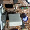
But I wanted to get the DC offset closer to zero. I had matched pairs lined up for Qe1-Qe4 but decided to start by increasing Re9 and Re10. While I was doing that, something bad happened and now I have 33 vdc (sic) at the right speaker terminals. I don't know enough to trace the problem but after hours and hours of trying, I noticed power transistor Qe22 is cracked (photo). Whether that is the cause of my 33v speaker load or a consequence, you know better than I. There's no smoke, no smell, and the dim bulb tester doesn't glow.

I do have a second KA-3500 waiting. I could nab Qe22 from that one, but I'm leaning instead toward putting #1 on the shelf and giving #2 the full recap I was planning for it. There's talk on Hopjohn's thread about substitutes for the unobtainable power transistors, so it's possible that I'll get #1 back in service eventually.

While I am here, what is the function of Ce36 safety capacitor, next to the fuse?
 

Attachments

  • IMG_2968.JPG
    IMG_2968.JPG
    186.1 KB · Views: 22
> the offset, you didn't say but I am
> sure that your offset is negative

No it was positive. Reducing Re9 and Re10 to 820 ohms took me farther from zero. Using 2.2k ohm resistors is as close as I got before things went amok on the right channel.
 
Update: Qe6 was shorted from base to emitter. I replaced it, kept the output transistors, matched the transistors Qe 1-2 and Qe 3-4, and got it all back together somehow. Paired with my Bang & Olufsen S45 speakers (1976), it's like going back in time. This was essentially my hifi through high school and college too. Now I'm going to restore my other KA-3500. It's a bit later and I already see differences (for example the Ce29 and Ce30 have three terminals: fortunately I have read Hopjohn's thread several times or that would have thrown me off my horse).
 
Last edited:
Back
Top Bottom