• The move to the new server is done. There are some software and database maintenance updates in process. This has us passing the hat around to help out. We appreciate any donations. Seriously, even a dollar helps. The payment page may be found here - https://www.audiokarma.org/support.html

Accuphase E-302 Help Needed

AngelAT

Well-Known Member
Hello fellow AKs!
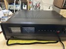
Finally I was able to get an Accuphase amp. I was reading about them being the Japanese equivalent of McIntosh, so wanted to see how they are made and how they sound. I am a fan of McIntosh and admire the support they give and also the enthusiast community. But my first impression regarding the Accuphase is a bit different...
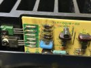
I got the E-302 defective - one channel has a few crispy transistors. And I struggle to find the service manual for the model. I tried all my usual sources but unfortunately nothing. Huge difference compared to McIntosh!
Can someone share their experience? Have you worked on an Accuphase E-302 and if so do you have a SM? I will at least need the part of the schematic for the power amps and then for the settings.
Otherwise I am quite impressed by the built quality and the looks.
Thanks in advance!
IMG_7853.jpegIMG_7837.jpeg
 
Register to hide this ad
Hello! Anybody? Hasn’t anyone been there? I know I can reverse engineer based on the other channel but still…
 
Might possibly only be the lower resistor that flamed. The rest might be peripheral heat and smoke damage from that resistor.
 
Thanks @Dave1027 for stepping in!
You are most probably right. I will check all of them. What I was thinking looking at this is that this resistor might be an emitter resistor for a failed transistor. But still, the schematic could be of use .
Do you own the service manual?
 
No.

You might try using an ohmmeter with one lead connected to the burned resistor and the other probing around for transistors or fets that connected to it. It's probably the ones located closest to it.
 
Last edited:
Makes sense. Will also check the traces. But you are right most probably it will be one of the closer transistors. I just hope it’s not one of the output transistors.
 
What is strange though is that there is no service manual for this model. I was able to find for other models but for this just a prospect.
 
You could dip an old toothbrush in isopropyl and scrub the area. It might help to see the damage of the burned resistors.
 
I just finished a repair on one of these last week. The unobtanium rectifier failed when an output transistor failed. Replaced both half wave rectifiers with standard bridge rectifier. Two of the four 10,000uf caps were getting warm. Replaced all 4. The service manual is available for download from several sources. I had a different version with silver front panel and rotary switches. It is likely only cosmetics.

The standard procedure for checking for shorted transistors will likely find the culprit(s). The failed rectifier I had was a surprise as they rarely fail.
 
Last edited:
I just finished a repair on one of these last week. The unobtanium rectifier failed when an output transistor failed. Replaced both half wave rectifiers with standard bridge rectifier. Two of the four 10,000uf caps were getting warm. Replaced all 4. The service manual is available for download from several sources. I had a different version with silver front panel and rotary switches. It is likely only cosmetics.

The standard procedure for checking for shorted transistors will likely find the culprit(s). The failed rectifier I had was a surprise as they rarely fail.
Thanks for the insight @d3imlay !
Happy that you were able to fix yours!
Based on advice I got in contact with Accuphase and they said they cannot help. No SM, no spare parts, etc.
Can you please share any of the places I can find the SM? Or, email me yours (if more convenient). We are speaking about e-302, right?
 
My mistake, I had a 202. I found a 302 users manual which had a general schematic. It doesn't appear to be too complex. Use a meter to check all of the transistor and diode junctions. Compare readings with the good channel. Replace only the parts that are confirmed to have failed.
 
I am slowly starting to make progress as it's now obvious there is no SM (at least publicly) available for this model.
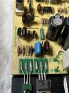
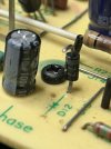
@rickl , you were right, I cleaned the area with some IPA and only the lower resistor is burned. The others measure ok. The burnt one is the emitter resistor for Q8 (A1360). This is a pre-driver if I understand correctly. The output transistors on this side are OK. So far the other components I have checked look OK. Will continue digging...
IMG_7989.jpeg
 
A quick status update and a few questions.

So I was checking components and I can say all diodes are ok. The output transistors are ok, the complementary to the A1360 is ok, the bias transistor is ok. The big WW emitter resistors are ok.
So I might be lucky and only have to replace the pre-drivers. And here comes the first question:

What should I use to replace A1360/C3423?

I see different options being suggested. Will mje340/mje350 do the job and be better than ksa1142/ksc2682?

Or there is probably a better replacement combination?

The what was interesting was that the other channel has a diode gone wrong and a stressed transistor:
IMG_8018.jpeg
D12 and R23!

The diode has the following markings: 5.F 77. My question here is may I use a super fast diode such as 4004 or 4007 here? This diode looks like the one used in power supplies. Or should I go with 1n4148?

I also replaced 2 capacitors as they were bulging, even tho they were measuring ok. The recapping is scheduled for after resuming proper operation.

Thanks in advance!
 
Kta1381 & Ktc3503 are the most similar 2SA1360/2SC3423 replacements that are currently available.

Also the symbol underneath D12 looks like one for a zener diode.

Id remove D12 from the working channel and check if its a zener before putting a standard diode in.
 
Thanks @Tala Mink ! I’ll order the replacement transistors. For the diode I think it’s a normal one:


IMG_8020.jpeg
I was thinking it looks like a power supply one…
Has anyone seen that particular one in any other Accuphase?
 
I've been into and through an E-202, but they are likely not very similar. I did find that several of the resistors are apparently designed as almost sacrificial to protect the circuits, particularly in the 717-0004-000 power supply board on that. Lots of heat stress, marginal cooling, and punished diodes and pass regulation trannys. If the 303 is the same in design (conceptually) you might find more signs of age and heating.

Using the A1381 would likely require a good connection to that heat sink, since the raw dissipation of that is only 1.2W versus the 7W with a heat sink.
 
Should be a regular diode then, the mark in the first photo made it look like a zener symbol.

A fast diode is probably a fine replacement, If the diode is from a voltage rail to the amplifiers output make sure its rated for at least twice the rail voltage.

Judging by the size id guess its a 1-1.5 amp diode.
 
Thanks for the insight @d3imlay !
Happy that you were able to fix yours!
Based on advice I got in contact with Accuphase and they said they cannot help. No SM, no spare parts, etc.
Can you please share any of the places I can find the SM? Or, email me yours (if more convenient). We are speaking about e-302, right?
You can't get the schematic or SM for this at present. Accuphase's answer is have your credit card ready and send it to their service, in the country where it was purchased new from. Until somebody leaks that SM one day. Neither will they sell you parts. Reality!
 
Back
Top Bottom