• The move to the new server is done. There are some software and database maintenance updates in process. This has us passing the hat around to help out. We appreciate any donations. Seriously, even a dollar helps. The payment page may be found here - https://www.audiokarma.org/support.html

Acoustic Research LST-2 .... Drug them out finally

Thanks guys, how much does it normally run to repair the originals? I might have to look into that.

I took a meter to a pair the other day and from the back I was getting around 6. However today before work I tossed the meter on the front and was getting a very different reading from the exposed leads. I’d say the 1.0-.8 range. So does that mean I’ve got a break inside or is there something I’m doing wrong?

I have the surrounds on the way for the 10”. Hoping that I can get them squared away and move to the next phase of the project.
You should contact Chris for the costs. I don't want to throw numbers out there as I'm not doing the repair service.
Chris is a great guy, I'm sure you'll work out a good deal.
 
Thanks guys, how much does it normally run to repair the originals? I might have to look into that.

I took a meter to a pair the other day and from the back I was getting around 6. However today before work I tossed the meter on the front and was getting a very different reading from the exposed leads. I’d say the 1.0-.8 range. So does that mean I’ve got a break inside or is there something I’m doing wrong?

I have the surrounds on the way for the 10”. Hoping that I can get them squared away and move to the next phase of the project.

Yes, you are doing something wrong. You need to disconnect at least one lead at the driver, And then measure resistance across the two leads. You were measuring in circuit, and basically measuring the resistance of the whole circuit between your leads.
 
Very cool speakers - - - am keeping my eye on this thread for interest. The bad news is that you have to take the driver out of the circuit to measure its DCR - - let's hope you have push-on connectors. The good news is that with this method you will get accurate readings.:)

When you get the chance, post pics of crossovers.
 
Ok, that's what I was thinking. Prior to just testing on the front leads I actually pulled two drivers and pulled them out of the circuit. With that I was pulling 6 ohms on each driver, so I think it's going to be ok?

I have no clue why I was checking from the front copper leads, I think I was just on another train of thought and didn't actually think..... lol.

I'll pull all the drivers tomorrow and test them out, I'll also snap some pics of the drivers and the cabs in a better area. My garage is a cluttered mess, ugh..

The cabs are coming along, I'm trying to salvage as much as I can on the original wood/veneer. There are a few areas that had some bad spots but I'm using some great stuff and it really, really makes a big difference.

Pics (Better Ones!) to come tomorrow! I'll also take a few of the crossover inside and anything else I can see.

The serial numbers are 4 digits on this pair and I think they are one off from another. These are the serial numbers (7762-7767)
 
Last edited:
Well here is today’s update

Pulled the drivers on one speaker, of the 6 tweets I’ve got 4 working and 2 showing an open status.


However I have a question. The metal basket tweet all are working but showing about 4.9-5.1 ohms for me. Then I have two of the smaller tweets that are open and one showing 6.0 ohms.

My question is should the larger metal basket ones read the same as the single small one? Would it be ideal to have them gone through as well or am I just tossing money out the window for 1.0 ohm? Will it make a difference or is that acceptable? I want to bring these back up to where they should be.

Still digging through it and will pull the other 6 drivers on the other speaker. The surrounds arrived for the woofers and they will be on the bench soon.

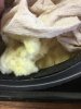
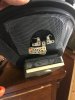
Interesting note, the woofer basket had some screen covers around the ports of the basket.

Here are a few pics, there is an interesting cloth like material behind the woofer basket to keep the insulation back.

More to come.

FB578B24-A2F1-4662-B8AE-494AD3398ADE.jpeg
AA3839DE-4DA3-48BE-A304-E06D0CD2CDBC.jpeg
D78937A9-D1D6-4CE9-A1AB-C2344C3CC5BF.jpeg
14346730-42D0-4E7A-A7F6-4969F0DAA536.jpeg
image.jpg
image.jpg
 
Just a small update

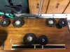
Woofers are almost finished on the surrounds. I have the new OEM fuse replacements coming in to swap in. The tweets are going to head out to our good AK'er to be reconditioned so that everything is back in tip top shape. I have been working on them when I can, I will also be working on the bottoms. Might look into some stands but I haven't found anything yet on what they are if they in fact came with some from AR.

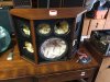
Picked up some other gear so I had to make some room and push things around. Nothing like an addiction right?
AR never had stands for these. I've seen several DIYs that have the top and base cut to the same shape as the cabs, supported by a couple vertice 4 X 4's. Height will need to be determined by you, but they were probably around 30 inches tall. Stained to match, they looked very nice.
Glenn
 
Thanks guys, how much does it normally run to repair the originals? I might have to look into that.

I took a meter to a pair the other day and from the back I was getting around 6. However today before work I tossed the meter on the front and was getting a very different reading from the exposed leads. I’d say the 1.0-.8 range. So does that mean I’ve got a break inside or is there something I’m doing wrong?

I have the surrounds on the way for the 10”. Hoping that I can get them squared away and move to the next phase of the project.
I'd shoot Chris a PM for the readings you're getting no the repair costs. Better info from the source than from us.
 
Hey Guys,

Sorry for the really long delay in getting back! I was out dealing with my wife's medical troubles and then my transmission in my truck gave out. So about 3500 later for that and a transfer case I'm finally back.

Now for a quick update on the LST-2's, I have the foams done and I'm in the process on wrapping up the other drivers that are out of spec to send out to Chris. I figured it would be ideal to have him address them so they are back to what they need to be. Once I get them back I'll re-install and get them back In action. As for the exteriors of the LST-2's, I'm going to go over them and see if I can clean it up some more. I done want to get too crazy as they are fairly nice as it, but naturally there are some dings and dents that other aspects to fix. I might try to see if they can get better without having to strip them all the way down and build it back up.

Stay Tuned, I will have more to come as I get back in action. I am picking up some speakers in the morning as well, Big....Altec....and should be fun for short money.

Thanks again for all those who were and are following the topic.
 
Correct me if I'm wrong — the fuses are in the signal path, correct? If so, it might be time to consider those pricey "audiophile" fuses. I wouldn't even consider buying them for an amplifier power supply. Snake-oil, IMO, in that application — but directly in the signal path....??
 
Actually, I purchased direct replacements from a place on ebay that specializes in these restorations. Here is a small part of the ad,

One CARTRIDGE FUSE for AR speakers LST and LST/2. Original AR specialty part. After some head scratching and trouble shooting we have now found several pair of these speakers with a soft failure. The fuses don't open but turn to high resistance. We now replace the fuse in all LST and LST/2 speakers that come in for repair. If your speaker suddenly has low volume across all drivers, replace this fuse before any other component
 
Correct me if I'm wrong — the fuses are in the signal path, correct? If so, it might be time to consider those pricey "audiophile" fuses. I wouldn't even consider buying them for an amplifier power supply. Snake-oil, IMO, in that application — but directly in the signal path....??

The argument against such products, which are neither tested nor approved by any testings body (UL, CE, etc.), is a series of facts.

Fact: The audiophile fuses are fabricated from silver.
Fact: Silver has lower resistance than the metal or metal alloys normally used in fuses.
Fact: The metal or metal alloy used as the fuse element has a resistance characteristic varying with temperature, and voltage drop vs. current is a curve instead of a linear relation.
Fact: The fuse element has a cold resistance and hot resistance.
Fact: If the resistance of silver is lower, the wire must be thinner to melt at the same point as the traditional fuse element.
Fact: If the wire is thinner, it will have greater heating at low frequencies compared to the thicker wire in a normal fuse.
Fact: If the wire is thinner, it will have lower thermal mass compared to the thicker wire in a normal fuse, and will faster cool as frequency increases
Fact: If the wire has greater heating at lower frequencies it has greater variance in resistance at those frequencies
Fact: If the wire has greater variance in resistance it has greater distortion.
Conclusion: The audiophile fuse creates, of necessity by way of being silver and thinner wire, greater distortion than a traditional fuse.

Quad erat demonstrandum.

 
When quoting this material please ensure that the attribution and citation are properly made to Bob Cordell's book, as these are his findings and statements.

Designing Audio Power Amplifiers by Bob Cordell, McGraw Hill, (2011)
"Fuse Distortion", "13.11 Fuse, Relay, and Connector Distortion", "Chapter 13: Other Sources of Distortion"
Page 269

When high current passes through a fuse, it heats up the fuse element by causing a small voltage drop that leads to power dissipation and temperature rise. The fuse element must therefore be resistive for this process to take place. The fuse blows when the temperature rises to the melting point of the fuse element. The fuse element has a positive temperature coefficient of resistance, so the process is accelerated as more current flows through the fuse.

At low frequencies the audio signal can heat up and cool down the fuse element within a single cycle, causing the resistance of the fuse to vary as a function of the signal amplitude. This leads to distortion because the attenuation of the fuse resistance against the load impedance changes as a function of signal swing [5]. Fuses are often undersized with respect to the peak audio current they may be called on to pass, recognizing that a smaller fuse will provide relatively more protection and that with normal audio signals, such high currents are brief events much shorter than the time constant of the fuse element. The cold resistance of a 2-A 3AG fuse was measured to be 78 mΩ, while its resistance when passing 2-A DC was 113 mΩ. This represents a 45% increase in fuse resistance.

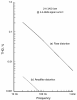
The distortion of a fuse can be measured by looking at the voltage across the fuse with a sinusoidal signal current passing through it. The fuse under test is put in the ground leg of an 8-Ω load resistor so that the signal voltage across the fuse can be easily analyzed. This technique largely takes the distortion of the driving source out of the picture. Figure 13.4a is a plot of fuse distortion versus frequency when a 2-A fast-blow 3AG fuse is passing a 2-A RMS sine wave signal. As expected, fuse distortion increases dramatically at low frequencies. Signal voltage across the fuse was 250 mV. Amplifier THD (due to the fuse) is calculated by normalizing the fuse distortion voltage to the amplifier output voltage. The resulting amplifier distortion is shown in Figure 13.4b. Amplifier distortion is lower than fuse distortion by a factor of 64 because of the small voltage across the fuse compared to the total signal voltage. At 20 Hz, amplifier distortion due to the fuse is calculated to be 0.0033%.

[5] Slone, G. R., High-Power Audio Amplifier Construction Manual, New York, McGraw-Hill, 1999.


Fuses THD vs. Frequency Designing Audio Power Amplifiers by Cordell (2011).png

Figure 13.4 THD versus frequency for a 2-A fuse passing 2 A RMS.
​
​
 
Just an update!

Got my drivers back from AK member CJVx and I'll be re-installing them hopefully over the holiday weekend. We ended up doing all 6 to give everything a fresh start and equal across the board. Top notch work and I'm thrilled to get these up and running. I think it's been a few years since these had any action put through them. So I'll keep everyone posted as it goes!

Retrovert - Thanks for the info, great stuff to have from such educated members!
 
I had a discussion with Roy C. at the last Frankenfest, and we were talking about the LST's & 2's and the fuses. He and Larry from "vintage-ar", who Roy does a lot of restoration work for had completely restored a set of LST's, but they didn't sound right. They rechecked everything over and over, scratching their heads. The only thing untouched were the fuses. They replaced them, and they sounded spectacular, so they do degrade over the years. Roy highly recommended I change mine, which I haven't done yet, just to make sure I'm getting the sound I should.
Glenn
 
Just an update!

Got my drivers back from AK member CJVx and I'll be re-installing them hopefully over the holiday weekend. We ended up doing all 6 to give everything a fresh start and equal across the board. Top notch work and I'm thrilled to get these up and running. I think it's been a few years since these had any action put through them. So I'll keep everyone posted as it goes!

Retrovert - Thanks for the info, great stuff to have from such educated members!
Chris does terrific work. Looking forward to your listening impressions.
Glenn
 
Back
Top Bottom