and the final wrap up of the threshold phono pre.
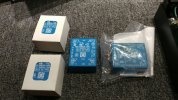
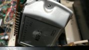
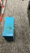
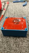
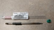
a difficult component to source in this day and age, thank you nsw.au (time-tunnel). txf in bag obviously the bad/replaced component.
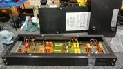
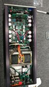
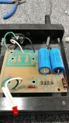
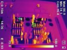
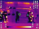
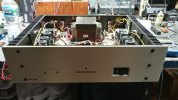
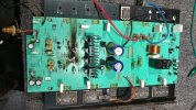
a frontal shot to help make sense of the thermals posted earlier. the 470uf 35v orange towers near the center of the preamp seem to have little electrical importance. each pair is in parallel in addition to the 10uf axial (green) film cap and there is maybe 7.5mv of dc across the caps (one trio per channel, with reference to chassis ground) regardless of mm/mc jumper selection. a potential update might be to reduce the 470+470 down to one 100uf muze series of electrolytic plus maybe another film (radial) to further decrease esr. or it might be a complete waste of components too, further design study, and a schematic, needed.
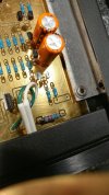
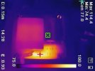
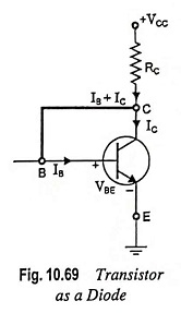
the front right corner hot spot mentioned during the thermal rant earlier. using a 1w 2% 5.6k to reduce thermal intensity by 50f. also updating a component (resistor) that is constantly subjected to the full rail to rail dc supply. if the resistor has a bad day, say goodbye to another txf. no fuses nor electrical protection, someone must have been smoking some stellar granola or something, although i have encountered far worse circuit designs. it is also interesting to note the transistors that are hugging the orange electrolytics, collector and base are shorted and being used as a rubber diode.
The transistor can be modified to operate as a diode by short circuiting the two transistor terminals, as shown in Fig. 10.69 [collector and

www.eeeguide.com
Hi does anybody know what's the purpose of the Q1 and Q2 transistors, sounds to me like they are constant current sources. Am I wrong? Could somebody explain me the purpose of those Q1 and Q2 tran...

electronics.stackexchange.com

en.wikipedia.org
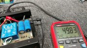
happy new-old-stock txf from the land down under (vegemite optional, 1922 inception) plus measuring +/- 25vdc output off of the filter caps. the preamp is stamped with 15v which must be the transistor amp internal parameters vs power input required.
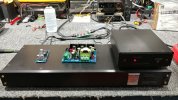
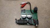
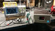
all back together plus a couple of "new tech" visitors. line level to phono (anti-riaa) adapter board in the background. makes it easier to test phono input on receivers without hauling out yet another table. the preamp indicator light is so recessed it may as well not even exist (manufacturer went too deep). the small and large boards are dc to dc buck boost regulators. i used the small board with its 12vdc input to create +/- 15vdc to test the preamp while waiting for the txf shipment. not realizing 15v is a bit too low for the main dc rails which are normally 25v, oops but it still worked.
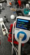
mains numbers, no dim bulb active, showing how little the system should consume, 6va txf is 6w assuming 100% power factor. the 40w dim bulb (single) is too high and might not protect the system is it goes nuclear again. should have used a 10w for circuit protection. this photo also shows dim bulb kaboom detector version 2.0 vs earlier in this oddity of a forum thread.
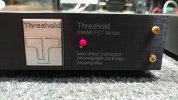
one last glamour shot of a rather nice "sounding" phono preamp. simple cosmetics, nice contrasting color scheme, when a black/dark chassis is utilized. this photo has a mediocre color balance, at best.
next up, the unusual root cause of power issues on a kenwood kr-7050, yeah its a weird one. and yet lighter than the rotel rb-1090 (-2 version) that nuked a channel (also next).




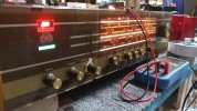














 It would cost a small fortune to replace them in those with the smoother sounding RDO replacements though.








 ....
....