A legendary Silicon Valley electronics emporium is having a moving sale with by-the-pound discounts (yes, really), so of course I had to pop in today after work and poke around.
In addition to some test leads for my scope, for a song I scored 3 identical power transformers marked 9-80-120 that look to be from a MusicMan 1600B SS bass guitar amp. I haven't mapped them out yet, but the data on them I can find indicates the primary has 100V and 120V taps and the secondary is 67VCT with a secondary current capacity of 2-3A.
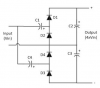
My Silvertone 1484 employs 2 voltage doublers in it's power supply. There are 2 secondary windings on the PT at 80V. Each secondary is connected to a bridge doubler comprised of 2 diodes and 2 capacitors. The two doublers are then connected in series to create the ~450V B+.
What I'd like to do with these MusicMan transformers is similar... and they have enough current capacity that driving two doublers off of them should not be an issue. They should be good for 375V @ 500mA (or 425V at something less than 500mA if I used the 100V primary).
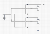
I *think* I can get away with simply building two separate doublers in parallel (by tee'ing each end of the transformer winding) and then connecting the outputs of the two doublers in series. See attached schematic. In this configuration, I would leave the center tap of the secondary disconnected.
The only thing I'm unsure of is whether the inputs to the two doublers need to be isolated from one another as they are in the Silvertone power supply.
My electronics-fu is not particularly strong, so a sanity check from the AK experts would be greatly appreciated
(I figure, even if I can't do what I want with these things, they hardly cost me anything and I can still find something to do with them...)
In addition to some test leads for my scope, for a song I scored 3 identical power transformers marked 9-80-120 that look to be from a MusicMan 1600B SS bass guitar amp. I haven't mapped them out yet, but the data on them I can find indicates the primary has 100V and 120V taps and the secondary is 67VCT with a secondary current capacity of 2-3A.
My Silvertone 1484 employs 2 voltage doublers in it's power supply. There are 2 secondary windings on the PT at 80V. Each secondary is connected to a bridge doubler comprised of 2 diodes and 2 capacitors. The two doublers are then connected in series to create the ~450V B+.
What I'd like to do with these MusicMan transformers is similar... and they have enough current capacity that driving two doublers off of them should not be an issue. They should be good for 375V @ 500mA (or 425V at something less than 500mA if I used the 100V primary).
I *think* I can get away with simply building two separate doublers in parallel (by tee'ing each end of the transformer winding) and then connecting the outputs of the two doublers in series. See attached schematic. In this configuration, I would leave the center tap of the secondary disconnected.
The only thing I'm unsure of is whether the inputs to the two doublers need to be isolated from one another as they are in the Silvertone power supply.
My electronics-fu is not particularly strong, so a sanity check from the AK experts would be greatly appreciated
(I figure, even if I can't do what I want with these things, they hardly cost me anything and I can still find something to do with them...)