• The move to the new server is done. There are some software and database maintenance updates in process. This has us passing the hat around to help out. We appreciate any donations. Seriously, even a dollar helps. The payment page may be found here - https://www.audiokarma.org/support.html

Adcom GFA 555 II - AC fuse question & fuse holder needed

plresults

Active Member
A fellow gave me is subject amp today for free. He only said it does not work and that he changed the fuses.
Upon inspection:
- the switch in back was in mono-bridged position, so perhaps why he thought broken
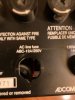
- the fuse in the AC fuse holder is a 20A fuse, way above the 12A spec.

Two questions:
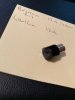
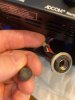
- does anyone have a spare new or used AC fuse holder to sell me? Existing is so chewed up that it can't be screwed with screw driver. (pic below)
- would ANY usage with a 20A fuse in place in that 12A slot mean fried electronics? Or just if an unusual load came through? I know that 20A fuse in a 12A fuse spot is a huge no-no.

Also, spec on the amp calls for a damping of 800, well above my Yamaha M2 rated at 200, IIRC. Is the 800 going to sound different/better for my rock. prog, funk, blues music, or is that improvement too small?

Gracias Amigos

thumbnail
 

Attachments

  • adcom 555 mk ii fuse holder broken_1-1_2022.jpg
    adcom 555 mk ii fuse holder broken_1-1_2022.jpg
    76.3 KB · Views: 21
Register to hide this ad
Perhaps more important is that the internal fuses for the DC supplies (7A) have not been altered. They perform the protection for the amplifier boards, whereas the line fuse protects the transformer and the unit in general from catastrophic overload.

Adcom's part number for the line fuse holder is FH052, but I'm betting a nickel that a standard Bussmann HKP or similar panel fuse holder can be retrofit into its place. I'd almost bet a dime that the Adcom "special" part number is actually an HKP.

For your reference, the complete service manual and schematic are available at HiFiEngine for free downloading.
 
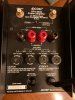
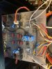
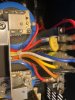
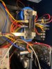
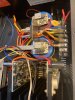
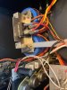
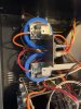
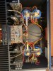
Hi: There is nothing inside that looks like a fuse. There are no fusable caps that appear to be exploded or burned up on any of the boards. The AC fuse holder appears as manufactured, but the nut is a bit chewed up. The four DC line fuses all appear intact. I am going to order the fuse holder as per your appreciated links, and a new AC fuse, replace the four existing non-AC fuses (as I've been fooled in past on old fuses looking good but but being bad), and go from there. The interior is pretty darn clean, with appearance of never having been worked on. Pics below. Your insights, opinions and speculations very welcomed! p.s. That transformer is a ridiculously large bit, ai'na?
 

Attachments

  • adcom 555 mk ii_ 1_2_2022_No10.jpg
    adcom 555 mk ii_ 1_2_2022_No10.jpg
    101.8 KB · Views: 22
  • adcom 555 mk ii_ 1_2_2022_No9.jpg
    adcom 555 mk ii_ 1_2_2022_No9.jpg
    70.8 KB · Views: 20
  • adcom 555 mk ii_ 1_2_2022_No8.jpg
    adcom 555 mk ii_ 1_2_2022_No8.jpg
    76 KB · Views: 21
  • adcom 555 mk ii_ 1_2_2022_No7.jpg
    adcom 555 mk ii_ 1_2_2022_No7.jpg
    117.9 KB · Views: 24
  • adcom 555 mk ii_ 1_2_2022_No6.jpg
    adcom 555 mk ii_ 1_2_2022_No6.jpg
    105.5 KB · Views: 21
  • adcom 555 mk ii_ 1_2_2022_No4.jpg
    adcom 555 mk ii_ 1_2_2022_No4.jpg
    126.6 KB · Views: 21
  • adcom 555 mk ii_ 1_2_2022_No5.jpg
    adcom 555 mk ii_ 1_2_2022_No5.jpg
    121.3 KB · Views: 21
  • adcom 555 mk ii_ 1_2_2022_No3.jpg
    adcom 555 mk ii_ 1_2_2022_No3.jpg
    115.5 KB · Views: 21
  • adcom 555 mk ii_ 1_2_2022_No2.jpg
    adcom 555 mk ii_ 1_2_2022_No2.jpg
    117.8 KB · Views: 23
  • adcom 555 mk ii_ 1_2_2022_No1.jpg
    adcom 555 mk ii_ 1_2_2022_No1.jpg
    146.1 KB · Views: 22
Last edited:
The DC fuses were those that I called "internal" since they are not line fuses. You can get spares, and test the original fuses with a meter for condition, then replace as necessary.

As for replacement of the line fuse, used the specified size but strongly consider using a Dim Bulb Tester to start the unit, at least initially. Something took out the fuse more than once for the cap to be damaged so badly.
 
I just realized there were more questions in your original post.

That is an interesting thought about the bridged/stereo switch, I don't know what would happen if it were used incorrectly. I have two GFA555 II's and I have run them bridged in the past but never experimented like that.

My first suspicion would be the 20A fuse was used because someone didn't have a 12A and didn't bother finding one. I just don't see it blowing a 12A fuse yet work with a 20A fuse.

Amplifier damping factor isn't something I've paid much attention to. It may be one of those things that makes one amp sound different from another but someone else will have to comment on that one.
 
I just realized there were more questions in your original post.

That is an interesting thought about the bridged/stereo switch, I don't know what would happen if it were used incorrectly. I have two GFA555 II's and I have run them bridged in the past but never experimented like that.

My first suspicion would be the 20A fuse was used because someone didn't have a 12A and didn't bother finding one. I just don't see it blowing a 12A fuse yet work with a 20A fuse.

Amplifier damping factor isn't something I've paid much attention to. It may be one of those things that makes one amp sound different from another but someone else will have to comment on that one.
The manual mentions that you will only hear left channel if the bridged switch is engaged when trying to listen to stereo. Prior owner said no sound whatsoever, so doesn't seem like that was his issue. Would ANY usage with a 20A fuse in place of correct 12A have caused a catastrophic failure? Or just extended time/loads? He said he never got it to work at all.
 
Since the 12A fuse is apparently not present nor available, we cannot know what type it was, and cannot guess as to why it failed. The same with the 20A fuse. An AGC is different from an SFE, which is different from an MDL or MDX fuse, which is different yet from a 3AG, and yet they can all be 20A fuses and fit in the holder. Moreover, there is a good change that the branch circuit used to power the unit is protected by a 15A breaker of fuse, and almost certainly no more than 20A, rendering whatever is installed now relatively meaningless.

The fact that the fuse failed is merely an indication. Analysis should be performed with the attempt to determine why it failed, and that could be concurrent with the attempt to understand why it is malfunctioning. The first step in that could be replacing the damaged fuse holder and installing the correct 12A standard curve (not time-delay) fuse and connect the DBT for a "safe" power-up.
 
The manual mentions that you will only hear left channel if the bridged switch is engaged when trying to listen to stereo. Prior owner said no sound whatsoever, so doesn't seem like that was his issue. Would ANY usage with a 20A fuse in place of correct 12A have caused a catastrophic failure? Or just extended time/loads? He said he never got it to work at all.

I didn't know what would happen if the amp was set to bridged operation but with the speakers still wired for stereo.

The 12A limit was chosen for a reason. At the same time, it may represent an abundance of caution. I've seen a few things over the years that had fuses rated below max output.

A larger fuse can't cause the problem, it can just allow it to get worse.
 
Back
Top Bottom