• The move to the new server is done. There are some software and database maintenance updates in process. This has us passing the hat around to help out. We appreciate any donations. Seriously, even a dollar helps. The payment page may be found here - https://www.audiokarma.org/support.html

Adcom GFA 555 Inspection Help

davestradamu

Swimming in Sound
Hello,
I got a GFA 555 a few months ago. It seems to work as it should and came from a reputable reseller. They were not sure if it was original or not, but it seems to work as it should and it sounds awesome to my ears.

How should I inspect it for repair or restoration work? I somewhat technically inclined and can use a multimeter to test things as well, I just need guidance to what/where to look and test.

Best,
David
 
Register to hide this ad
you can find the service manual/schematics on hifiengine. Whenever I get new piece of gear, especially vintage, I get my wizard tech to give it the goods..
I am not familiar with the Adcom products but someone will weigh in shortly.. .good luck
Thanks! Unfortunately, my options are limited where I live as there are no local techs I am aware of. I'd most like to take some basic measurements to make sure its not in poor health.
 
Most probably updates would be a recap and replacement of original (failed) transistors and maybe some burnt out resistors.
Open it up, check (photo) boards showing caps. Also check between left and right channel for any differences in resistors, transistors, new heatsink compound,,,
You could do an audit of transistors and compare with L&R sides and services manual however this may be out of date.
 
I picked up one today and will be looking it over after I bend a bit of metal back in place. Might check it out for working condition tomorrow before I do a lot of work on it.

After I find out it works, I'll look into the age of the parts and its performance. I have plenty of speakers that can put them to a test. Don't know if this one gets a recap or not but that is all after setting any internal controls to factory specs.

For you, you say it works, enjoy it. Read the OM and SM and learn the how to dial it in per the manual. Don't shove a meter probe in there and expect to touch what you want to touch without touching something that makes a spark and kills your amp. But minigrabber leads and do it the safe way. I do believe that all qualified and many unqualified folks repairing gear have had this happen. I lost a resistor in a turntable, killing the tt. Came back when I finally replaced the resistor, no further damage. Might not be that easy in this amp.
 
First Up: Check DC output. It's not adjustable, if it's out-of-spec, you need to replace parts.
Second, check output transistor bias.
 
Owned a few of them. Agreed, it sounds great but am less impressed by lack of speaker protection. Monitor DC offset often and play only with speakers that have little value. I have read too many stories here of expensive and rare drivers getting fried.
 
Those add on protection relay kits would be a great investment if you plan on using it with speakers you don't want to chance damage.
 
OK since I have one of these, I'm going to hijack @davestradamu's thread and do in it exactly what he wants to do to his amp. Not much of a hijack I don't think since he hasn't been here since his post. Hopefully we can have a good bit of info here for him when he checks back in.

The GFA-555 (not the mk II version) has 2 schematics on the web for the amp. One of them is for the earlier (I believe) version of the amp and the later version is the one shown in the pics, with part numbers on the input board in the 600 range. Be sure to get the schematic that matches your amp if you are going to need one.

I have checked the DC Offset of my amp and it is not good (40 and 70mV). After adjusting the bias which has no effect on the dc offset, I'm going to need to replace parts I guess.

First Up: Check DC output. It's not adjustable, if it's out-of-spec, you need to replace parts.
Second, check output transistor bias.

Can you point out the parts that need replacement? Guessing the input transitors Q601-604 the 2SC2362 and will need matched pairs using the currently out of stock KSC1845. Please correct me if I'm wrong and any further recommended replacements?

Those add on protection relay kits would be a great investment if you plan on using it with speakers you don't want to chance damage.

If I get this amp running right and it does sound good, I might want to list to it on speakers I don't want to source replacement parts. Can you recommend a protection circuit to install?

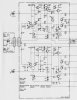
Attached is the scat for the amp I have.
 

Attachments

  • GFA-555 S-Input.jpg
    GFA-555 S-Input.jpg
    56.1 KB · Views: 29
Those add on protection relay kits would be a great investment if you plan on using it with speakers you don't want to chance damage.

Like the Bose 901, the 555 is one of the great survivors in audio. Both are still in production decades after they were introduced. Both have gone through revisions but the latest models are recognizable as descendants of the original. Some would opine that both products are flawed and yet, they have outlasted supposedly non-flawed designs. 555 with 901 would be the great survivor system. The original 555 with suitable updates (speaker relay is a must, IMO) and restoration would be the one to get as it is a pure Nelson Pass design. The Mk II had revisions done by Adcom designers not named Pass so it is not the same. There are some posts in other forums that state the 555 line is the single most produced amplifier in home audio. That may very well be considering how long it has been in production. Interesting stuff.
 
Last edited:
I have checked the DC Offset of my amp and it is not good (40 and 70mV). After adjusting the bias which has no effect on the dc offset, I'm going to need to replace parts I guess.


Can you point out the parts that need replacement? Guessing the input transitors Q601-604 the 2SC2362 and will need matched pairs using the currently out of stock KSC1845. Please correct me if I'm wrong and any further recommended replacements?
Sorry...Everything I know about Adcom amps I learned from reading other people's posts.

All that info will be available on the internet, probably on this very forum--but I don't remember the specifics.
 
No pbm. Not finding a lot and having two versions of the first model makes it more difficult to find the right info. For an amp that can be a problem, there doesn't seem to be a lot out there. Other amps I have are more discussed.
 
I've never tried to source a DC protection kit but there are quite a few threads about them. I do know there are Chinese options available on eBay. I would think it wouldn't matter where they came from as long as they disconnected the speakers if DC were to make it to the output.
 
Seems to be a lot of misinformation on these amps on the web. I've had this amp for a few weeks and haven't done much with it but did do the research. A few things folks will learn about the GFA-555;
The GFA-555 had both the rack mount faceplate with handles and the extruded faceplate with the ribs. I do not know if this indicates a time of manufacture. There is also a GFA-555 Pro with front panel circuit breakers for the rail fuses and it is a rack mount unit. Here is @hjames thread about the different physical versions of the amps. http://www.audiokarma.org/forums/index.php?threads/adcom-gfa-555-variations.272875/
The GFA-555 was manufactured with two different input boards. One mounts vertically on the center rear panel on standoffs and has a small board with the RCA jacks under it. The other board mounts horizontally at about the level of the RCA jacks. These are different and there are different schematics associated with them. More anon.
This original version is the one that was designed by Nelson Pass and it seems he didn't want protection circuits degrading the sound of the amp. This can be a problem if the amp dies while in use and takes out your speakers but there seems to be a large group of owners that have never had a problem with their unit.

The GFA-555 II is similar in looks but different in execution has its own issues and servo control to keep DC offset in check. This discussion is not about the II but its issues do cloud the GFA-555 reputation. One issue in the II is the leaking caps that contaminate the input board causing problems. This is not an issue with the better boards of the earlier amps, to the best of my knowledge. The leaking electrolyte would permeate the paper circuit board and it would affect the electrical characteristics of the II amp.

The vertical input board schematic is on HFE labeled schematics. https://www.hifiengine.com/manual_library/adcom/gfa-555.shtml

The pdf labeled service manual has schematics for the other (horizontal) input board. It is not what I have in the vertically arranged board but I don't know much more about this one. I'd have to get one and compare it. That schematic is probably available on the web with better legibility as I think I saw it just didn't grab it. The difference is the numbering of the transistors, starting with Q1 in the horizontal board numbering and with Q601 on the vertical board. The vertical board is copyright 1986. Hope this helps some.

 
Last edited:
One of the most important modifications you can make to the GFA-555 is adding an input blocking cap. This machine is DC-coupled from in to out,and any DC offset on the input will spell disaster for your speakers. I use 1ufd/63v film caps for this,which with the 22k input impedance gives a -3dB point of around 8hz.

I have checked the DC Offset of my amp and it is not good (40 and 70mV). After adjusting the bias which has no effect on the dc offset, I'm going to need to replace parts I guess.


A DC offset of 40mV to 70mV is really not bad at all. Consider this as a decimal value, 0.040V to 0.070V; this is 40 to 70 thousandths of a Volt.
A quick Ohms law calculation reveals that 0.070V across 4 Ohms works out to 0.001225 Watts dissipation in the speaker. Still worried?:)
 
Yes, not bad at all but swapping the diff input pair could lower that to the ±40 or less that these amp seem to be able to do. They aren't ones that will do zero DC offset for some reason.
 
Back
Top Bottom