• The move to the new server is done. There are some software and database maintenance updates in process. This has us passing the hat around to help out. We appreciate any donations. Seriously, even a dollar helps. The payment page may be found here - https://www.audiokarma.org/support.html

Adcom GFA-565 service

Racingh11

Super Member
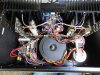
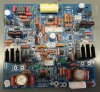
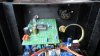
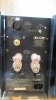
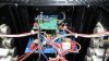
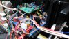
I finished restoring a pair of these amps. They both had DC offset issues among other things. After messing around with the original board on the first one, I found it had current leaking into the DC servo opamp ground reference. I removed everything from the trace and it was still there around 15V and varying with noise. I purchased new driver boards for both amps. Along with top precision resistors, silver mica caps, new transistors, etc. In the end they tested .0032 and .0033% THD and .0007 and .0008% IMD. S/N was > 116dB. at 300W into 8 ohm. They also got all new electrolytic capacitors.

They sure sound good, although the smell of the speaker coils in my woofers isn't pleasant. They have been pounded up to 250W for years, but this 300W+ took a toll on them today.
IMG_0438.JPG IMG_0401.JPG IMG_0426.JPG IMG_0429.JPG
 
Last edited:
Register to hide this ad
Nice work! I didn't know there were in existence, MPSA13's or 63's with CBE pinout instead of EBC. (Looking at the face, left to right) Did those come with the original board or from elsewhere?
 
Thanks. I used BC516, BC517 instead of MPS. All of the transistors are new, and most of the other parts too. If I used the MPS series, I would have went with the MPSA14, 64 being the current preferred devices.
 
Last edited:
Interesting! Good to know those are an option. Minimum gain of 30,000 versus the A13/63's 5000. I've always wondered why Adcom spec'd these instead of the A14/A64... I don't think cost would really enter into that decision, it's only pennies different, and they were using nice expensive parts elsewhere, like silver-mica caps and such. So if it's not cost, then I thought maybe Walt Jung must have specified them in the original design for some reason, and so I've been erring on the side of not second-guessing that. Could there be any drawback to the higher Hfe bins? Might they become harder to match, or might they drift relative to each other more? Could the curves be flatter on the lower Hfe ones? The datasheets aren't much help in this regard. In any case, I'm sure your amp is working great, -2V on the DC servo is right on target.
 
I'd like to know why certain transistors are used in several amps I service. I'm sure there are a variety of reasons. From my experience, higher gains tend to have lower DC offset. They use MPSA29(darlington) in the differential on Soundcraftsmen MOSFET amps. They are easier to match than the non darlington stuff, even though they may range quite a bit in a batch of them. I try to get them within at least 500 of each other. Offsets usually end up 5mV or better, and that's on designs without a DC servo. I couldn't really say as to what transistors have more linear gain and junction voltages since I don't test them on a curve tracer. And like you said, the datasheets aren't real thorough on these for comparing apples to apples. I haven't felt the extra time to do that has had any benefits. On these particular amps, I would say there is going to be no real difference between any of the transistors we mentioned so far. And that is shown with the measured performance tests scoring better than rated, which is probably exactly how they were when new. With that being said, that may be the case for the military spec low noise resistors, and low distortion mica caps, etc. But, they are in there so it is going to be as good as it's going to get.

I actually don't remember what voltage that servo put out when done, but offset stabilizes to a perfect 0V.
 
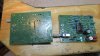
The pair is back for more upgrades. He wants balanced XLR inputs and a C13 power cord socket installed. Since the 565 had a balanced input board option, the XLR cutout is conveniently behind an added metal cover. No new or used balanced boards are available for these that I could find. So I am going to modify the input boards I designed for some Soundcraftsmen amps. It's almost the same as what Adcom did. Mine are designed for a stereo amp with switchable channel A bridging w/ switchable low-pass filter. And can support balanced inputs. I ended up only using 2/4 of the opamp sections. Jumpered some parts and left others out. Ended up with a balanced input to one opamp, outputted to a buffer stage. And with a pin removed from one switch to create a balanced/unbalanced input switch like the original had. When in balanced mode; it outputs to the unbalanced RCA, like the original. Could be used for daisy-chaining when switched to balanced mode. Since my boards are for through-hole components, I am also using adapter boards to take advantage of the SMD, OPA1604 opamp. Super low distortion and noise.

My input board will fit, but I may have to angle it slightly to clear the XLR connector so I can have the balance-switch button stick through the original gain adjustment hole. I could have used the stock bass boost pot. for gain control on the buffer section, but did not need it for the application. I also could have made low or high pass, and inverted outputs to connect a subwoofer amp or bi-amp with, and they would have their own turn-on muting delay. I added a resistor to the new designs(for stereo amps) I haven't printed yet, where it would allow mono channel A + B instead of just channel A mono and filter.

I will post some pictures soon. I'm waiting for opamps yet.
 
Wow, that sounds amazing!

Yes the OEM balanced option isn't anything special. Your version sounds better!

Also, the OEM balanced boards have the same exploding Elna capacitors, so even if you had one, it would probably be ruined anyway.

What's the clearance issue that you need to angle the board? Is it the height of heatsinks? It might be possible to mount the VAS transistors and heatsinks, up-side-down, so the heatsinks are hanging down. The transistors would then be mounted with their faces to the heatsink. Thermally this isn't as good, but I think it would still be better than OEM with those small heatsinks, and it's probably plenty good cooling.
 
It's the width between the heatsink and the XLR connector. The board is 2 inches wide and I want the switch to line up with the hole. So the hole locates the board to where it looks close. I'm waiting for the XLR connectors too. But one way or the other, it will fit in there.
 
The XLR connectors arrived. There will be plenty of clearance to have the board mounted level and the switch lining up with the existing hole. Just need to make a couple holes to mount the brackets.
 
I soldered the new opamps to the adapter boards and installed them in the input boards I just built. I have the boards and XLR hanging in there to show how it's going to fit.
IMG_0735.JPGIMG_0738.JPGIMG_0739.JPG
 
I have one board and XLR connector installed, and the power cord socket. The XLR connectors were angled slightly using the original holes, but should function just fine.
IMG_0747.jpg IMG_0748.JPG IMG_0749.JPG IMG_0750.JPG
 
Back
Top Bottom