• The move to the new server is done. There are some software and database maintenance updates in process. This has us passing the hat around to help out. We appreciate any donations. Seriously, even a dollar helps. The payment page may be found here - https://www.audiokarma.org/support.html

Adding a phono input to X-100-B and to a model 400 receiver using Tape Head input

klamsoss

Be willing to fail and try again.
This has been discussed in bits and pieces elsewhere but I wanted to bring it all together into a single thread that is accessible for folks like me, who don't have quite as much expertise as others.

I will begin with the X-100-B since it's the one I understand better. I'll need help addressing this conversion on the 400, which we can tackle in a subsequent post.

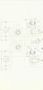
The attached screenshot is of the X-100-B input section as stock. It can be seen that there is no resistive loading on the Tape Head input. It can also be seen that the output from switch 1 that goes to the PEC eq circuit (which I have replaced with discrete components) is already joined. To me, this would seem to indicate that all I need to do to convert the tape head input to a phono input is insert whatever resistor value I want between the hot lead on the Tape Head input, and ground. Typically this would be 47k ohm but other values may be preffered for specific cartridges (for example: some folks like loading grados between 10k and 28k ohms).

Am I missing anything there?

What is unclear to me is how the X-100-B as stock presents a 47k load to the normal phono lo input. Based on the schematic, it would appear that the 220k and 56k are effectively in series and would represent a 276k load. What am I not understanding?

With some clarity on this, I hope to be able to reason out the specific modifications for the model 400 phono input section.
 

Attachments

  • Screenshot_20210612-143324_Drive.jpg
    Screenshot_20210612-143324_Drive.jpg
    34.7 KB · Views: 14
Register to hide this ad
What you are forgetting about is R7 and R8, which are each 56K resistors serving as the grid return resistors at the input of the phono preamp stage. When the Tape Head input is selected, with no other resistance to ground in the Tape Head input lead, the input impedance presented to the Tape Head is 56K. Nominally the generally accepted input impedance standard for this input was 50k back in the day, but the need for the input disappeared before any true standard could be set. An input impedance of 56K is certainly close enough.

In the phono input setting, an additional resistance of 276K (made up of the divider resistors R1, R2, R3, and R4) is now connected in parallel with the 56K grid return resistors, so that the phono LO input represents an input impedance of 46.55K, again, close enough to the 47K standard. Note that the Phono Hi input impedance is made up of a 56K voltage divider resistors (R3 and R4), in parallel with with the 220k divider resistors + 56K grid return resistors in series placed across the 56K voltage divider resistors. Again, the Ohm's Law math is the same for this input, so that even the Phono Hi input jack represents an input impedance of 46.55K as well.

I hope this helps!

Dave
 
Thanks Dave! This makes sense to me.
For the pictured X-100-B input, the extent of the loading modification for Tape Head input would be to add something like a 270k or 300k resistor to ground to achieve an equivalent parallel resistance reasonably close to 47k ohms. Other values can be achieved with different resistors, and are relatively easy to calculate using the parallel equivalent resistance formula.

Now that I understand the loading part of things, It seems like this is really a very easy modification. While I don't fully understand the switch diagram, I do understand that the input to the Channel A EQ circuit comes from "S1 Front" positions 5 and 6 (tied together) and for the Channel B EQ circuit it comes from "S1 Front" positions 11 and 12 (also tied together). Since these are tied, and the EQ switching is built into the PEC (or bypassed/eliminated, in my case, after implementing the RIAA EQ revision developed in a Dave thread elsewhere), all one needs to do is pop the parallel loading resistors in and keep their EQ slide switch in the "phono" position, and the Tape Head input jacks will function as a second phono input.

Handy for comparing two turntables or just having two different setups for different uses!

Okay, now for the 400....
The switching and loading setup is a little different here.
For one thing, there is no EQ slide switch on the 400, so getting signal from the selector switch requires actually wiring the correct "posts" to the proper point on the PEC or to your discreet RIAA filter, if you have one installed. The Tape Head input corresponds with the wire going to point "2" on the PEC. Disconnect that wire and attach where point "3" is, and you'll have both inputs leading to the RIAA filter. That part I understand.

Now, there is also a difference in how the loading resistance is achieved on the model 400 receiver. I'm going to reference the component numbers in the attached schematic, but for posterity: there are different versions of the 400 receiver, with different component numbering on the schematics. I haven't cross referenced things to know if the component numbers in this area are the same between both schematics, but it shouldn't be hard to follow along.

The grid return resistors (R51 and R52) are 100k, so assuming things work like they do in the X-100-B, something in the area of an 89k would yield a 47k equivalent resistance for the Tape Head input.
BUT I think I'm missing something....

Each channel of the phono low input first hits a 150k resistor (R47 and R48) in series with a 68k resistor (R49 and R50) and then these are paralleled at the input by a 220k resistor (R45 and R46). The resulting equivalent resistance here is around 110k ohms. Then we have the grid return resistors which are indicated as 100k ohms (R51 and R52). Unless I'm missing something (I probably am, which is why I'm here for help) this would result in the loading of the "phono low" input to be a bit over 52k ohms.
While that's close to 47k, it's not THAT close, and I can't imagine that Mr. Fisher would have had a design (especially one of his most popular designs) that was specified a full 10% off the ideal target value. Consequently, I'm guessing that I have overlooked something here, as well.

ALSO, there's the little C65/66 and R53/54 circuit, which I know has been mentioned in other places, but I don't really understand it.
 

Attachments

  • 400 receiver phono input schematic.jpg
    400 receiver phono input schematic.jpg
    82 KB · Views: 8
yep, 89k to end up with a 47k load at the tape head jack.

Looks like you're right on the stock setup coming out a bit above 50k. Probably considered it close enough since thats about as close as its going to be with standard value resistors. If you really wanted to tweak it, you could change that 100k grid resistor to 82k which would put the stock phono input awful darn close to 47k. If you did that, the resistor at the tape head input would need to be 110k.

I think C65/R53 is a ground loop breaker with a cap for EMI filtering. At high frequency the cap has a very low impedance so any RF trash would just go to ground. The 10 ohms is enough to help break ground loops so it won't be as prone to hum.


My TA-600 also uses a 100k grid resistor, I think I used a 100k at the input jacks simply because it was the closest thing I had on hand at the time. Comes out to 50k, but I wasn't inclined to wait on parts, and now that its back together I'm not real motivated to go back and mess with it.
 
Back
Top Bottom