Hi bill, what pins should I put them on?
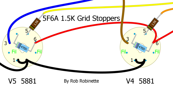
There are several ways. If you are only using the grid resistors then, Connect the resistor and connection from the Phase invertor to pin 6, then attach the other end of the resistor to pin 5. Pin 5 is the control grid input of the tube. pin 6 is unused by the tube.
If using the screen grid resistor then install the screen connection to pin 6 and the screen resistor ( 470 ohm 1w) from pin 6 to pin 4. you can install the grid resistor from pin 1 to pin 5 , PI connected to pin 1. Make sure pin 1 is not connected to 2 . Pin 2 is the cathode. Pin 1 is not used by the 6v6, its just a convenient tie point like pin 6.
Or you can fly the grid resistor , ala marshall, connect the PI to the end of the grid resistor and then the other end of the resistor to pin 5. this is not really the best way, but marshall did it because the el34 has a different pinout , grid 2 is not internally connected to the cathode, pin 1 is the connection to grid 2 . This is the diagram as posted by RWOOD .
I suggest googling fender layouts for the 5e3, and AB763. The problem comes when you try to use the original wiring, as the leads may not be long enough to run the PI to pin 1.
But , honestly this amp is fine as wired originally. The potential problems arise when amps have higher gain and or higher voltages and the wiring is more complicated.