• The move to the new server is done. There are some software and database maintenance updates in process. This has us passing the hat around to help out. We appreciate any donations. Seriously, even a dollar helps. The payment page may be found here - https://www.audiokarma.org/support.html

ADS L710 early crossover issues

Coachster

AK Subscriber
Subscriber
First of all, let me stress I have no idea what I'm doing.

It's a longer story than I care to share, but I'm putting the guts of a pair of L710's in a larger cabinet because the original cabinets were infested with field mice, one died, and I couldn't get the smell out.

I got everything together, wired up the 1st speaker, and it's great.

The 2nd speaker, the two woofers won't work. They both test fine on their own. Has to be the crossover, right?

Here's the crossover. Where do I start? (Yeah, I replaced the two 50uF caps with 47uF's. That shouldn't be an issue, right?FullSizeRender.jpeg
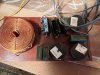
Thanks in advance.
 
Register to hide this ad
Replacement of the two 50 uF caps by two 47 uF caps doesn't explain the woofers not working, provided they are both in working order.

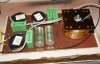
After some searching on the internet, I think that your crossover is identical to the crossover in the Braun L710.

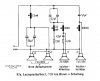
This is the schematic of the crossover of the Braun L710:

Crossover Braun L710.png

You could check if:

1) you did connect the two woofers correctly, in that both negative terminals of the woofers are in connection with the negative terminal of the input of the crossover, and the two positive terminals (marked 'rt' in the schematic) of the woofers are in connection with the point where the positive terminals of the two 47 uF electrolytic capacitors and the lower side of the 2.5 mH coil join (I'm pretty sure that the 2.5 mH coil is the big one on the left of your picture).

2) the upper side of the 2.5 mH coil is in connection with the plus terminal of the input of the crossover, because if it is not, no signal can reach the woofers

3) the lower side of the 2.5 mH coil is in connection with the plus terminals (marked 'rt' in the schematic) of the two woofers, because if it is not, no signal can reach the woofers

4) the 2.5 mH coil isn't interrupted internally, because if it is interrupted, no signal can reach the woofers

5) one or both of the 47 uF capacitors you installed isn't shorted, because if one or both are shorted, no signal can reach the woofers

When you test for continuity with a multimeter (use the lowest Ohm setting), it's best to disconnect the mid and the tweeter, and disconnect the crossover from the amplifier. In that way there are no paths for dc (which a multimeter in the Ohms range uses to measure resistances) other than through the part of the crossover intended for the woofers.
 
You used electrolytic caps? Hmm. Pretty sure you'd want non-polarized caps for this...

(not saying this explains why one speaker doesn't work now, but it might be an issue over time...)
 
I'm certainly not very knowledgeable when it comes to the pros and cons of electrolytics versus non-polarized capacitors in crossovers. On the picture of the crossover of the Braun L710 they look like electrolytics to me. The schematic also shows them as electrolytics.

Braun L710 Crossover.jpg

Source: http://audio.mezei.fr/pages/BraunL710.html
 
FWIW, there were electrolytics on there when I opened them up, and I just replaced what I saw.
 
Back
Top Bottom