
• The move to the new server is done. There are some software and database maintenance updates in process. This has us passing the hat around to help out. We appreciate any donations. Seriously, even a dollar helps. The payment page may be found here - https://www.audiokarma.org/support.html

ADVENT 300 RF Coil

Hello, I’m an extreme novice in audio restoration and need some advice - usually get by with schematics and posts on this forum.
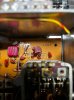
I bought an ADVENT 300 amplifier, but is not working at all. I found some concerning things on the tuner board and took some pictures - I have no idea what this is.

2 Questions, if someone is willing to help,
1) The components that seem to be failing are labeled as RF Coil (Yellow), which is exactly what they are, but what can I replace them with? I looked on Mouser, but no luck.
2) What is and how do I remove the solid amber mess fused to the circuit board?

Thanks in advance. Look forward to hearing back.
 

Attachments

  • 4E8B7124-26CB-4F7F-9555-EC3D959BD647.jpeg
    4E8B7124-26CB-4F7F-9555-EC3D959BD647.jpeg
    92.9 KB · Views: 13
  • 81890B53-14A3-434D-B48D-C7383757808C.jpeg
    81890B53-14A3-434D-B48D-C7383757808C.jpeg
    103.9 KB · Views: 12
  • 3D8D6AA2-7A09-483C-8110-802DD8F5C0FF.jpeg
    3D8D6AA2-7A09-483C-8110-802DD8F5C0FF.jpeg
    143.6 KB · Views: 12
Register to hide this ad
That is the antenna tuning coil. very doubtful it is bad. What is the symptom you are trying to fix? Do you have any test equipment?
 
That is the antenna tuning coil. very doubtful it is bad. What is the symptom you are trying to fix? Do you have any test equipment?[/QUOTE
The unit gets power, but doesn’t have much power. I do have a Hantek Digital Oscilloscope (barely know how to use - did not come with manual), a couple of variacs, a DBT, and a signal generator (but will probably use an app on my phone once I get to that stage).

Thanks
 
Honestly, I noticed the power was poor (sound low and distorted) months ago. I was just looking to see if there was a blown cap or something obvious (which I have not found ever), but then noticed the melted wax pushing the tuning coil away from the circuit board and though I found something.
I think I’ll clean it and put the coils back today and see if I can measure it more accurately - get back to you this week.
 
Honestly, I noticed the power was poor (sound low and distorted) months ago. I was just looking to see if there was a blown cap or something obvious (which I have not found ever), but then noticed the melted wax pushing the tuning coil away from the circuit board and though I found something.
I think I’ll clean it and put the coils back today and see if I can measure it more accurately - get back to you this week.
In order to help you and save time, I will sometimes ask you more than one question in my posts, so you need to read my posts carefully and respond to all questions.
Is it low on both channels?
 
The Wax may be there to hold the coils steady and in place, it isn't a sign of failure - don't clean it off if you have never worked on RF equipment before!
 
In order to help you and save time, I will sometimes ask you more than one question in my posts, so you need to read my posts carefully and respond to all questions.
Is it low on both channels?
Okay - will do my best.
I put the RF coils back and carefully soldered them.
I measured the power supply : + 21.6 VDC on F400 (service manual stated +24 +/- 10%), so good.
: - 20.36 VDC on F401, so a little low
Bias read 0.117 - 0.118 across R330 and R332, but could not adjust using R316 (service manual recommends 0.003 VDC).
0.094 - 0.111 across R331 - R333, but again could not adjust using R317

Hooked it up to my oscilloscope - 400 Hz signal input with minimum volume - unable to get consistent reading. My first time to use this approach, so I am probably doing something wrong, but the AMP started to heat up across the heat sink and my DBT lit up.
Reset fuse
Attached speakers and AUX tape player - no sound from Right channel, Left channel was clear, but balance did not shift all the way to right (still able to hear left).

I’ll work on measuring distortion, but since I could not get much signal from right channel, may be why my measurements were not very helpful?
 
Okay - will do my best.
I put the RF coils back and carefully soldered them.
I measured the power supply : + 21.6 VDC on F400 (service manual stated +24 +/- 10%), so good.
: - 20.36 VDC on F401, so a little low
Bias read 0.117 - 0.118 across R330 and R332, but could not adjust using R316 (service manual recommends 0.003 VDC).
0.094 - 0.111 across R331 - R333, but again could not adjust using R317

Hooked it up to my oscilloscope - 400 Hz signal input with minimum volume - unable to get consistent reading. My first time to use this approach, so I am probably doing something wrong, but the AMP started to heat up across the heat sink and my DBT lit up.
Reset fuse
Attached speakers and AUX tape player - no sound from Right channel, Left channel was clear, but balance did not shift all the way to right (still able to hear left).

I’ll work on measuring distortion, but since I could not get much signal from right channel, may be why my measurements were not very helpful?
Idle current is way too high, like 300mA! Don't power it up again until instructed. One or both output transistors may be blown. Start testing the output transistors, starting at the output and working back toward the input until you stop finding shorted transistors. Test both channels. Be sure to test Q312 and Q313 as well.
 
Thank you all for your welcome. Sorry for the prolonged response - my soldering station stopped working (soldering gun) and had to order another.
So far I have been able to check Q312 (2SC1345E) with the following results
+ - Q312 Q313
Base Emit - 0.703. 0.700
Base Coll - 0.695. 0.696
Emit Base - OL OL
Coll. Base.- OL. OL
Coll Emit. - 0.639. OL
Emit Coll. - OL. OL

These seem OK to me? I hope this notation makes sense - tried to follow previous threads.
 
Back
Top Bottom