• The move to the new server is done. There are some software and database maintenance updates in process. This has us passing the hat around to help out. We appreciate any donations. Seriously, even a dollar helps. The payment page may be found here - https://www.audiokarma.org/support.html

Aikido 12Vac line stage/pre-amp build & review

If the volume pot was wired wrong chances you would get a garbled sound or noises. Ask me how I know. :biggrin:
Even if it was shorted I wouldn't think it would cause the preamp to draw a lot of current. Go over all your wiring and solder joints very carefully. It may be something grounded that shouldn't be. Also check all your electrolytic capacitor orientation. One last thing. Check the plug on your wall wart. Some have the center connector as ground instead of the outer part.
 
Last edited:
  • Like
Reactions: MKG
All caps and diodes are installed correctly and it was glowing nicely at all the right voltages until I temporarily attached wires/rca jacks/volume. I was just using twisted pair from cat 5 cable cause I just wanted to hear it- wire is pretty weak. I’m guessing one broke and is touching something it shouldn’t be.
 
That initial fire-up is indeed frightening.

I've built three cheapie Chinese "clone-type" line stage kits recently.
Basically, no info at all.
First one I assembled blew a polarized axial cap...but not my fault....the pcb was silkscreened incorrectly.
Swapped in better caps with the correct orientation and believe it or not, it's dead quiet and actually sounds pretty good.

Last one I put together made a truly awful noise on power-up. I shut it down fast.
Nothing cooked itself, but I suspect I may have the power supply hooked-up wrong.
When I get my nerve up I'll try again.

Having no schematics is a real problem if you're as electronically ignorant as I.
 
Yeah, I’ve stayed away from the cheap Chinese clones after struggling with a couple “kits”.
I’ll try them out again down the road.
 
...after a bit of troubleshooting, here’s where I’m at.
If nothing other than power is plugged in, or power and output connected, all voltages are right where they should be.
The second I connect an input (not just a cable to an input- the cable has to actually be connected to an input source that is on, even if that source is paused and not putting out a signal) it shorts out and throws the breaker.
Any ideas?
 
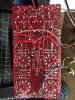
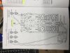
Here’s the board from both sides in case I’m missing something obvious.
EDF8CCF2-CBCF-415B-93C0-A04E93CA4DC5.jpeg 13DD6755-283F-4D06-831B-4D0F2D8E63A6.jpeg
 
Long shot, above symptoms reads like a grounding issue, ie, a mismatch between the RCA outer ground
connection from your source and the aikido GND. Check your aikido GND path/connections.
 
Long shot, above symptoms reads like a grounding issue, ie, a mismatch between the RCA outer ground
connection from your source and the aikido GND. Check your aikido GND path/connections.
I'm only seeing grounds connected to the board only. If you have some jumper wires with clips play with the grounding. Like from board ground to chassis. Is there an earth ground for this board, or does it just run off of a two prong wall wart? Also looking at the top of the board I see what looks like a sliver of solder from the (+) to the (-) at one of the inputs. Is there a drawing of the board and how its wired that you can post? Also post the schematic.
 
Hard to say for sure, but looking at the pic of the bottom of the board, it looks like the green signal wire may be connected to ground and the white [ground] is connected to positive.

On the other hand, maybe there's another twist to the wires that I can't quite see?
 
Last edited:
No solder blobs or shorts between points on the board.
Board isn’t grounded as it’s not in a case- and it’s powered by a two prong wall wart (actually a variac, currently
CD729A9F-F98D-46AF-9AD5-D253B32B0879.jpeg7783014B-BFED-4DE6-9263-6849014877A7.jpeg867EF5B1-B3F6-4DE7-9226-88771831A9AE.jpeg
 
Right now it’s not in a chassis so it is most definitely isolated.
I think what he's saying is the incoming GND from the wallwart(?) should not be connected to the Aikido GND. Will take another look at the pix.
 
  • Like
Reactions: MKG
I have an insulated power jack that will be used once it’s chassis mounted in order to isolate the jack from the chassis. Right now the jack is floating in free air as it’s not chassis mounted- I’m attempting to test run it before I mount it in the chassis and fully assemble everything such as the multiple inputs, etc.
Thank you all for your efforts to help me with this project- I’d be lost if it wasn’t for AK.
 
The "wallwart grounding" is a red-herring, it does not explain why all ok until a source is connected.
Did you confirm that the green wire is connected to the +/input and not ground as per below post. White wire looks ok...
Hard to say for sure, but looking at the pic of the bottom of the board, it looks like the green signal wire may be connected to ground and the white [ground] is connected to positive.

On the other hand, maybe there's another twist to the wires that I can't quite see?

upload_2019-4-19_14-33-28.png

Maybe try with one rca cable from source say Left then repeat test with right cable only...
 
There’s another twist there, wires are appropriately going to positive and ground.
I haven’t isolated left and right to see if one causes the short and one doesn’t- thank you. I’ll give that a shot and see if I can narrow it down to one channel.
I also sent another email to the designer of the circuit in hopes that someone else had this issue.
 
It looks like you have it wired right. The power supply is AC voltage out right? Not DC? And the power supply can handle the current draw of the board?
 
Back
Top Bottom