• The move to the new server is done. There are some software and database maintenance updates in process. This has us passing the hat around to help out. We appreciate any donations. Seriously, even a dollar helps. The payment page may be found here - https://www.audiokarma.org/support.html

Aiwa SA-P50 Distortion on both channels

Cosmic_S

New Member
Hello and Good Day/Afternoon/Evening to everyone
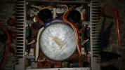
so my father has this Aiwa SA-P50H that he bought a few years ago and its all original but has an issue, sound comes out distorted (mostly on one channel, the other one its almost indistinguishable but its there) going by memory

so the amp behaves as follows:

Amp turns on and relay connects speakers successfully, however the led scale on the front lights up to the 3rd led (0.5W mark) with no audio input

i took some measurements with the help of the Service Manual
(i never turned on the amp more than 30 seconds at a time, enough to measure voltages and shut it down immediately)

DC Voltage at speaker terminals
Right Channel= around 6.0mv and goes down slowly
Left Channel= around 0.4v and doesnt seem to go down much if at all

Zero Potential (DC Balance) (supposed to me 0mv +-3mv)
Right Channel= 5.6mv and seems to go down slowly
Left Channel= about 0.4v about the same as speaker terminals

Idle Current Adjustment (Bias) (supposed to be 8mv)
Right Channel= 0.014mv-0.007mv
Left Channel= 54.4mv (yikes)

so since i dont have much experience yet i was hoping for help in what to check, i assume at the very least check everything on the left channel driver board, but id like to avoid de-soldering and taking things out more than absolutely necessary

(i have attached the amp schematic as a PDF because the image is being compressed)

As always any help is greatly appreciated
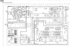
1748052362817.png

1748051932367.jpeg
 

Attachments

Last edited:
Register to hide this ad
ok i did some further testing and the right channel doesnt respond to bias adj, dc offset adj works correctly, left channel responds to both adj but wont go low enough to be within spec
 
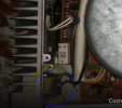
OK. Step one is replace the RIFA switch suppression capacitor over the power switch. It is not anything to do with the problem, but it will have cracked and if it hasn't exploded, it will soon.

1748165939327.png

They are epoxy encased, the epoxy cracks, the air/moisture gets in and 'boom'- the capacitor explodes.

I would say you have some output stage failures and likely a few other issues. It's a very simple amplifier and uses decent quality components. Built around 1980/1 or so IIRC. There were some fusible resistors which are known to drift, but you have two dead channels (?) and potentially an unstable front end (the meters are indicating). Check your voltages on a DBT* and also check your OPT (output transistors) for functionality. Also the emitter resistors (~0.22/0.33R).

dim bulb tester or equivalent voltage/current limited supply.

This era of AIWA mini components was a great period. The late Heitaro Nakajima (of Sony and the engineer behind compact disc) was in charge of AIWA through and during this time. Some fantastic products built. I've got a pile of their other mini-components and snap them up whenever I see them.
 
Last edited:
I would say you have some output stage failures and likely a few other issues. It's a very simple amplifier and uses decent quality components. Built around 1980/1 or so IIRC. There were some fusible resistors which are known to drift, but you have two dead channels (?) and potentially an unstable front end (the meters are indicating). Check your voltages on a DBT* and also check your OPT (output transistors) for functionality. Also the emitter resistors (~0.22/0.33R).

dim bulb tester or equivalent voltage/current limited supply.
channels arent dead per se, both have distortion, (right channel more than left one, and right channel doesnt respond to bias setting at all, left is way over-biased and with a huge dc offset) dim bulb is the first thing i did and it didnt light up at any time, not even when trying to play music briefly

anyway just today i finallly dissasembled this amp almost completely and tested the outputs on a "GM328 Transistor Tester" which isnt a replacement of an actual LCR meter but its better than nothing, anyway heres the results the device threw of the otputs

Left channel, Q15 (2SC2525): • Device type: BJT NPN • Pin order: 1-2-3 = B-C-E • hFE (gain): 26 • I_E (emitter current): 6.142 mA • V_BE: 590 mV • I_CEO leakage: 750 nA • C_BE capacitance: 2.547 nF Left channel, Q17 (2SA1075): • Device type: BJT PNP • Pin order: 1-2-3 = B-C-E • hFE (gain): 80 • I_E (emitter current): –6.272 mA • V_BE: 626 mV • I_CEO leakage: 19 nA • C_BE capacitance: 2.391 nF Right channel, Q16 (2SC2525): • Device type: BJT NPN • Pin order: 1-2-3 = B-C-E • hFE (gain): 25 • I_E (emitter current): 6.154 mA • V_BE: 611 mV • I_CEO leakage: 10 nA • C_BE capacitance: 2.493 nF Right channel, Q18 (2SA1075): • Device type: BJT PNP • Pin order: 1-2-3 = B-C-E • hFE (gain): 53 • I_E (emitter current): –6.321 mA • V_BE: 626 mV • I_CEO leakage: 17 nA • C_BE capacitance: 2.387 nF

also double checked them with a dmm on diode mode and they conducted only in the right ways,

so before i was done for the day i measured a few resistors around in-circuit and found one on the main pcb that was supposed to be 10ohms read as 1 ohms, and on the right channel driver pcb one that appears to be a 100 ohms one read 12.7k and another one appeared to be open

so i will have to keep going meassuing resistors and diodes and cross-referecing them with the other channel and parts list (as much as the low quality pcb components drawing allows)
 
ok so after a couple of weeks of slowly testing, measuring and taking notes of the results so far ive found 5 components to be replaced which are:

R47-R49 have drifted way way up into tens of K
R48 and R50 which have done the same thing,

also i found that with the help of a gm328 Q11 (left channel driver 2SC2591) to have its HFE to be way way off, left channel one is at 50 while right channel one is at 124
idk if this could be throwing off the bias and dc offset on the left channel and its not Q1 or Q5

i will also add the spreadsheet where ive added all the parts ive measured so far if anyone wants to take a look at them

Aiwa SA-P50H Parts List Spreadsheet

i would add the spreadsheet to 1st post too but apparently am not allowed anymore
 
Last edited:
ok so i have fixed this amp
problem parts were R47-R49 and R48-R49
also Q11 had an a very low hfe of 50 while q12 had around 130

pulled q11 from another p50, replaced those resistors with same 1/4 watt rating,

turned on amp with DBT, made sure excessive bias and dc offset were gone they did

warmed up amp, adjusted bias and dc offset to spec and it was done,

now it plays music cleanly, negative feedback look works by dialing bias back when it gets hot,

i think it should be fixed, with hopefully many years more of service
 
Back
Top Bottom