I recently pulled out my receiver I had in high school but found there is distortion on both left and right channels whether I'm playing FM of phono. I also tried another set of speakers. A friend suggested the filter capacitors are the issue but I'm sure a total recap is best. Any advice before I dive in would be greatly appreciated!


You are using an out of date browser. It may not display this or other websites correctly.
You should upgrade or use an alternative browser.
You should upgrade or use an alternative browser.
Akai AA-1115 Distortion
- Thread starter Infoseek
- Start date
-
- Tags
- aa-1115 akai distortion
Register to hide this ad

Ylli
Super Member
Fix the problem first, *then* consider a recap. Both channels the same - equally distorted? Start by measuring the rail voltages. Easiest access is probably at the fuses (F4/F5 or F6/F7). Use caution and do not short anything when making measurements. Then measure the output DC offset of both channels - voltmeter across the speaker output terminals. No speakers need to be connected for these measurements.
Yes both channels seam to be equally distorted. With the power switch off F4 thru F7 = 20v. With the power switch on F4 and F7 = 15v. F5 and F6 = 24v.
Your question about the output DC voltage across the speaker terminals with no speakers connected. I guess I'm showing my ignorance here because I have the receiver set to FM and the voltage is all over the place. From .07v to 1.0v DC. I have a feeling this isn't what you asked for.
Your question about the output DC voltage across the speaker terminals with no speakers connected. I guess I'm showing my ignorance here because I have the receiver set to FM and the voltage is all over the place. From .07v to 1.0v DC. I have a feeling this isn't what you asked for.
Ylli
Super Member
With power off, there should be zero volts at the fuses. [edit: After turning power off, the voltage will ramp down taking a number of minutes before reaching zero] Let's confirm your measurement techniques....With the power switch off F4 thru F7 = 20v. With the power switch on F4 and F7 = 15v. F5 and F6 = 24v.
Assuming a digital multi-meter, or DMM. Set it to the DC volts mode, or if it is not autoranging, set it to the 200 volt DC range. Black lead need to be connected to the amplifier chassis, and the red lead used to probe. F4 and F6 are the same point electrically, as are F5 and F7. After power has been off for a while (5 minutes), you should read zero volts at these point, and with power on, the schematic says +28 and -28 volts.
The output offset should be measured with the volume control set as low as it goes, and an unused input selected (e.g. Aux). You want to see if there is any significant DC offset at that point and don't want any AC (audio) interfering.
OK I understand now. I waited for the voltage to drop to zero then turned the receiver on. F4 and F6 = +24.2 and F5 and F7 = -24.
I then turned the volume down to 0 and switched the input to Aux. My meter isn't auto-ranging so on the 200v scale I get .01v and on the 20v scale it's .07v.
I then turned the volume down to 0 and switched the input to Aux. My meter isn't auto-ranging so on the 200v scale I get .01v and on the 20v scale it's .07v.

Not significant..pretty much normal..t .01v and on the 20v scale it's .07v.
Ylli
Super Member
Since it is both channels, we are looking for something common to both channels. If cleaning doesn't help, let's finish confirming power supply voltages.
Measure the voltage at the emitters of TR16 and TR17 as shown by the arrows. Emitter of TR16 (red arrow) should be 13.3 volts. Emitter of TR17 (blue arrow) should be +24 volts.
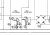

Measure the voltage at the emitters of TR16 and TR17 as shown by the arrows. Emitter of TR16 (red arrow) should be 13.3 volts. Emitter of TR17 (blue arrow) should be +24 volts.
Is it safe for plastics?I have a can of CDC Electrical cleaner
Ylli
Super Member
The rails and this are a bit low, but not to the point that it should cause distortion.emitter of TR17 is reading +21v. Are these too low?
Yes it says "Plastic Safe" Thanks!Is it safe for plastics?
Well thanks for being patient with me and helping me check the voltages!The rails and this are a bit low, but not to the point that it should cause distortion.
The rails and this are a bit low, but not to the point that it should cause distortion.
After a lot of cleaning on the pots and switches the distortion is now only on the right channel. I waited a day to let the clean dry and when I turned the receiver on R47b went up in smoke and the fuses in F6 and F7 both blew. I replaced R47b and the fuses but now anytime I connect a speaker to the right channel I get a loud hum and the fuses blow.
Ylli
Super Member
Don't connect a speaker to that channel until you get the problem solved. It sounds like you may have blown one or both of the output transistors. With both speakers disconnected, redo the offset measurements we did earlier - DMM across the speaker terminal, volume at minimum, input set to aux, etc. If the offsets are not below 0.5 volts, you will need to remove TR10b and TR11b and test with your DMM on diode mode. https://audiokarma.org/forums/index...-transistor-testing-basics.43186/#post-390997 . If either of these are bad, you will need to replace them both with modern replacements. If they are bad, you should also remove and test the drivers, TR8b and TR9b.
Don't connect a speaker to that channel until you get the problem solved. It sounds like you may have blown one or both of the output transistors. With both speakers disconnected, redo the offset measurements we did earlier - DMM across the speaker terminal, volume at minimum, input set to aux, etc. If the offsets are not below 0.5 volts, you will need to remove TR10b and TR11b and test with your DMM on diode mode. https://audiokarma.org/forums/index...-transistor-testing-basics.43186/#post-390997 . If either of these are bad, you will need to replace them both with modern replacements. If they are bad, you should also remove and test the drivers, TR8b and TR9b.
OK with both speakers disconnected, input is set to aux, and the volume is all the way down I have 23.4 volts on the right channel. Wow! I have a decent meter ordered that should arrive tomorrow. I have followed the link you included above and will remove the transistors before testing. You mentioned replacing the 2sd313 transistors with "modern ones". One website I went to suggested the NTE152 as a replacement but if you or anyone has a better idea I would appreciate it.
Last edited:
Ylli
Super Member
NTE is not too well though of either. I would recommend using KSD880YTU, https://www.digikey.com/product-detail/en/on-semiconductor/KSD880YTU/KSD880YTU-ND/1052401 is one source. But do test them before ordering replacements as there are other things that could cause a high DC offset on the output.
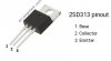
*From EchoWars Post "Set your meter for diode test, and place the positive lead on the base. Place the negative lead on the emitter. You should read a diode drop voltage of about 0.45 to 0.65V. Now place the negative lead on the collector. You again should read a diode drop of about 0.45 to 0.65V (these values are not written in stone...the 0.45 to 0.65V is the most common range however). Now place the negative lead on the base, and the positive on the emitter (called 'reverse biasing'). There should be no conduction. Now move the positive to the collector, and again, there should be no conduction. Lastly, move the negative to the emitter. Again, there should be nothing."
Following the quote from EchoWars post above and the image I included, here are my readings. I removed both components from the board and set the meter for diode test.
Testing TR10b my positive lead on the base and negative lead on the emitter I get .027v. The negative lead on the collector I get .028v. The negative lead on the base and the positive on the emitter I get the same reading of .028v. Because I should get no conduction here this one's bad right? Then with the negative lead on the Base and the positive on the collector I get .028v once again.
Testing TR11b my positive lead on the base and negative lead on the emitter I get .097v. The negative lead on the collector the meter beeps and I get .0020v. The negative lead on the base, and the positive on the emitter I get .097v. Finally the negative lead on the Base and the positive on the collector the meter beeps and I get .0021v.
Following the quote from EchoWars post above and the image I included, here are my readings. I removed both components from the board and set the meter for diode test.
Testing TR10b my positive lead on the base and negative lead on the emitter I get .027v. The negative lead on the collector I get .028v. The negative lead on the base and the positive on the emitter I get the same reading of .028v. Because I should get no conduction here this one's bad right? Then with the negative lead on the Base and the positive on the collector I get .028v once again.
Testing TR11b my positive lead on the base and negative lead on the emitter I get .097v. The negative lead on the collector the meter beeps and I get .0020v. The negative lead on the base, and the positive on the emitter I get .097v. Finally the negative lead on the Base and the positive on the collector the meter beeps and I get .0021v.
Attachments
Confirm this is with your DMM set to "Diode" mode. The numbers you see are unusually low even for bad parts.
After further review TR10b is reading 1.16v across the base and emitter and a short across the base and collector. TR11b is shorted out on both measurements. I ran to a local electronics shop for a second opinion. He said they were both shorted out.
Last edited: