• The move to the new server is done. There are some software and database maintenance updates in process. This has us passing the hat around to help out. We appreciate any donations. Seriously, even a dollar helps. The payment page may be found here - https://www.audiokarma.org/support.html

Akai ap-d33 issue

P. S.
After repairing is advisable to perform a complete recalibration of the electronic circuit, following the instructions written in the service manual (easily available on the net).
This operation require only a digital multimeter of good quality (currently it's possible purchase one of these instruments with a few Euros/Dollars).

When I try to adjust off-set voltage, and torque difference (VR4, VR5 and VR6 according to manual), I can't just measure a steady voltage on those parameters.

I follow the steps in the manual, (short the indicated pins etc), and when y measure pin 1 to GND, result is near -100mV but is not a stable value.
I noticed that if I move closer or far away from the turntable, the values measured change in a noticeable way, I suppose that there is same magnetic field playing its roll... but I can´t figure out how to solve this.

Also, the last step where I should adjust VR6, when I measure pin 1 or pin 2, the value I measure changes from few -mV to few +mV randomly (need to move to the 2 Volt scale in the multitester), so I cannot set a parameter for VR6.

Any idea of what can be causing this?

Maybe other electrolytics caps?

I thought about the tester probes, those are just standard chinese, not like the one the comes with o-scopes... (I don't have an o-scope!), maybe they need some filtering or sth?

Thanks
 
A little guide to solve the problem:
  1. Open up the turntable and spray a deoxidiser inside the pitch control and 33/45 selector switch; operate repeatedly these controls to facilitate the action of deoxidiser and then wait a few minutes for complete evaporation of the product.
    Sometimes this solves the problem.
  2. If previous operation didn't allow resolution of the problem, then go to check all electrolytic capacitors and replace those that are not in optimal conditions; this obviously requires use of a capacitance/ESR meter.
    If you don't have these tools, then replace all electrolytic capacitors (these electronic components are cheap and easily available).
  3. In my case problem was the presence of a high loss capacitor (C6 - 0,47 μF/25 Volt).
    This faulty capacitor was responsible of a partial short-circuit to ground of the transistor TR3 piloting signal with the consequent failure of the speed control circuit.
    Replacing this capacitor the problem was completely solved.
    To conclude maintenance, I replaced the resistor R15 (= 10 kOhm) with a 12 KOhm resistor and the resistor R16 (= 8,2 kOhm) with a 10 KOhm resistor. The reason for this replacement is that, with the original resistors, the right speed was achieved only by turning trimmers VR1 (33) and VR2 (45) fully counterclockwise (max resistance).
    With this simple change also this problem was completely solved.
P. S.
After repairing is advisable to perform a complete recalibration of the electronic circuit, following the instructions written in the service manual (easily available on the net).
This operation require only a digital multimeter of good quality (currently it's possible purchase one of these instruments with a few Euros/Dollars).


Thanks for the info, it helped my alot.
i had the same problem with the speed at 33. sprayed some deoxidiser inside the pitch control and 33/45 selector switch. tweaked the trimmer VR1 (33)
and it was fixed !! hope you will read this. Thanks mate !
 
[*]In my case problem was the presence of a high loss capacitor (C6 - 0,47 μF/25 Volt).
This faulty capacitor was responsible of a partial short-circuit to ground of the transistor TR3 piloting signal with the consequent failure of the speed control circuit.
Replacing this capacitor the problem was completely solved.

Super! This really all it took to fix the delay problem.
I replaced the C6 with a 0,47µm / 35 V instead of 25 V. It worked perfect! I even could use the trimmers VR1 (33) and VR2 (45) fully again. So I did not replace the resistor R15 and R16. There was need for that.
Thanks alot from the Netherlands
 
I have Akai AP-D40 - do you know if that is the same as D30/D33?
I found such a information here: http://www.stereo.net.au/forums/index.php?/topic/32906-akai-ap-d30-speed-problem/
There you can find information about capacitors:
C2 - 100uf 10V
C5 - 0.47uf 16V
C6, C7 - 3.3uf 16V.
Values above are different from that you wrote.
Will be work for D40?

Yes, the values you’ve quoted are correct for the AP-D40, but not the AP-D30 or AP-D33, which use slightly different circuits. So replace them all with exactly the same capacitances (as originally fitted to your AP-D40), with electrolytic capacitors having equal or higher voltage. That should eliminate any current or future speed problems.

So for the 10 volt capacitor, you could safely use ones with equivalent capacitance, and of 10 volts, or 16 or 25 volts (provided they fit in the space!) if a 10V one isn’t available, and for the 16 volt ones, you could use 25 or 35 volt ones, if 16V ones aren’t available. The main thing is that their rated voltage limits are never exceeded, so you can’t use ones rated lower than the originals for working voltage.
 
Hi everyone, been lurking around here and a couple other sites trying to resolve the issue with my Akai AP-D30. Got it used and when the guy showed it to me I didn't realize that the strobe for the 33 speed was lined up when the table was set to 45 speed...Either way, I adjusted the internal variable resistors to the max and I got very close but still not quite up to speed.

So I read up on here about changing the capacitors out. So today I headed down to my local electronics store and picked up replacements for the 4 capacitors outlined in giancarlopel's amazing guide. (Thank you giancarlopel!) Just to be safe I picked up some contact cleaner as well and sprayed that on and twisted till my wrists hurt. And low and behold! It was exactly the same as before. Needless to say, I was bummed but I wouldn't be deterred.

Thinking about giancarlopel's guide again I checked out the two resistors in question R16 and R15. Using the service manual at vinyl engine for the AP-D40 it was clear that the 8.2K R16 was for 33 speed and that the 10k R15 was for 45 speed.

I sought first to change the 33 speed since so far, all of my collection is in that format. I figured that less resistance would mean faster platter so I put in a 6.8K resistor. Surprisingly I found that my table was even more slow than before. Puzzled but hopeful I tried more resistance than the original 8.2K with a 10K resistor. Cranked up the table to find that it was now too fast! No problem, I turned VR2 back down a bit while I watched the strobe finally come to a standstill.

Eventually I'll probably change out the other resistor for 45 speed but couldn't be bothered right now. I know that this is probably not fixing my real problem but as far as I'm concerned, my songs play at the proper speed again! Anyways, I know nobody is currently looking for an answer to this but if someone had posted this before my trip to the electronics store I would have saved myself a lot of time and money because I had the resistor in my electronics box anyways. Oh well, at least I know the caps are good too!

Hopefully in the future someone will find this and not have to go through all the trouble I went to in order just to get their turntable up to speed.
 
Hope this thread still alive..

I have replaced c6 capacitor but still the problem persist. Now the motor is making shrieking noise.
When i check on the motor connector on the pcb board by connecting multimeter to pin 8 & pin 10, i noticed there is a continuity from pin 8 & pin 10.

Now i'm stuck. Any advise or the Pcb have a shor circuit?
 

Attachments

  • IMG_20150602_021108.jpg
    IMG_20150602_021108.jpg
    126.1 KB · Views: 48
  • IMG_20150607_130604.jpg
    IMG_20150607_130604.jpg
    116.9 KB · Views: 48
Hey, I just got a AP-D30 and I am having the 33 speed issue. Going to change the resistors out and see what happens. When I turned it on, I smelled that electrical burning smell. I'll post once I change out the resistors.
 
Replacing C6 did the Job for me.
I replaced it with a 0,47/50v capacitor.
Also deoxing the pitch control, and the VR1 and VR2 .
The pitch control can only be sprayed from the bottom. only that side is open.
And like other people said: work them plenty times back and forward. Then rest , spray again, wait , back and forward.
Then leave the deoxit overnight to dry.
Its worth it !
 
Holy thread revival, Batman! I picked one of these up for $20 because the previous owner said the speed wouldn't lock. Easy-peasy fix I thought. Cleaning the main pitch control did not solve the problem. Accessed the 33 & 45 trim pots on the board and although 45 stabilized, 33 would not. I decided to re-cap the board and this also did not solve the problem. Thanks to this thread, I replaced R16 & R15 as per the values listed above. Bingo - both speeds have more than enough "turn" on the pots now to achieve speed lock with the pitch control. I cleaned and re-oiled the main bearing and she's running great. The D33 has some seriously ugly and useless feet. I replaced them with some taller, more substantial ones from an old Toshiba deck I had sitting around and now it sits much taller and looks great. One thing I'd like to try is stuffing some modelling clay within the empty portions of the chassis as the D33 is not the most substantial deck weight wise.
 
Last edited:
Holy thread revival in the new century, Batman! I've also picked up this TT in a rather sorry state, around 20 RPMs on the 33 and around 34 on the 45. What I did:
  • trimpot recalibration - no luck, still out of range
  • trimpot cleaning - still no luck
  • complete recap and replacement of R15 to 12K and R16 to 10K - almost perfect
There was however one thing missing - almost always when switching from 33 to 45 (and back) the TT would drift for a long while, then stabilise, and sometimes go drifting again for a while. I was replacing the 1KB pot, when I thought of something I ommited!
I dissasembled the speed selector switch assembly and sure enough there was a nasty buildup inside which reduced the contact quality. I sprayed it with the pot cleaning spray, worked it back and forth a couple of times and now it works perfect.
Just to conclude: remember to clean the switches along with the pots!
 
Thanks for letting us know about your fix, ogisha007, and for the original fix, giancarlopel - I must have missed seeing that. I'd replace all the other electrolytic capacitors while I had it open - if one has failed, chances are the others aren't far off it. Still, after 30 years they've had a good life - I've had ones fail recently in modern electronics just out of warranty:no:.

Edit: oops, I see giancarlopel also suggested replacing them all. I should read things more carefully. Oh well, you can never have good advice too many times.:D
Dont you think that old capacitors that lasts more than 30 years are more reliable than new capacitors that can go faulty in one or 2 years?
I would suggest changing only faulty capacitors!
 
Dont you think that old capacitors that lasts more than 30 years are more reliable than new capacitors that can go faulty in one or 2 years?
I would suggest changing only faulty capacitors!

Well, yes, if they’ve lasted 30 years or more, they were more reliable than ones which have only lasted 1 year and 1 month (appliance warranty usually 1 year, annoyingly!). :rolleyes:

However, if I’m going to replace one electrolytic capacitor that has failed due to an age-related problem (dried out electrolyte etc), over 40 years of experience in electronics has taught me that I might as well replace all of them, at least if I own the appliance. If one has failed due to age, some others are probably also close to failing, so I prefer to be safe, than spend time in the future pulling the PCB out again to replace others. I can imagine that some people to whom every cent is precious might not want to do that, so I’d probably take a different approach if people were paying me money to repair their equipment, and would replace only the faulty item(s).

However, that doesn’t mean that I don’t agree with you about some modern equipment having capacitors which are very unreliable. I’ve also experienced capacitors failing just after the warranty (usually 1 year) on the appliance ran out, and when I replaced them, the appliance started working again. That is possibly more likely due to the designers working to a cost budget, and specifying the lowest voltage ratings possible, which possibly weren’t quite high enough for reliability, given that they were barely adequate or perhaps specifying capacitor brands which were the cheapest possible, but which didn’t necessarily meet their supposed specifications.

I’ve found that usually name brands such as Panasonic tend to last a lot longer than the cheaper brands for electrical appliances (and components), probably because they are more concerned with their quality reputation, rather than chasing as many sales as possible with the lowest costs.

I’ve also been recently burnt by some very cheap Chinese-manufactured metal film resistors I bought, advertised (and colour-coded) as being 1% tolerance, which was nothing but a dream – 5% tolerance was closer to the truth, I’ve sadly discovered.:whip: They were very cheap, if not always suitable for everything I wanted to use them for, so I’ll find uses for them where tolerance isn’t critical.
 
Last edited:
I’ve also just restored a knackered D33. Changed a few dodgy caps and cleaned the speed adjust trimmer pots as mentioned above.

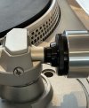
Mine also had the perished counter weight rubber and I found a nice, simple fix.
Rubber cable grommets. Two and a half small ones fitted perfectly inside the black plastic piece and then a slightly larger one fits to the tone arm itself.
Cut a small notch out for the extended key bit(?) The original screw down the middle, jobs a gooden!
 

Attachments

  • IMG_0018.jpeg
    IMG_0018.jpeg
    109.6 KB · Views: 16
Last edited:
Back
Top Bottom