• The move to the new server is done. There are some software and database maintenance updates in process. This has us passing the hat around to help out. We appreciate any donations. Seriously, even a dollar helps. The payment page may be found here - https://www.audiokarma.org/support.html

ALIGNING TUNER - TEST EQUIPMENT CONSIDERED?

jisake1

New Member
Considering options to best align a KENWOOD KR-4140 as manual specifies. First job I worked in a Montgomery Wards service center. Was laughable when you opened a tuner sold then which came with a steel weight inside. Was installed only to make a customer think they had a large power supply. :bs: Was trained to tune a unit by ear at MW. As a result, have never used an oscilloscope or frequency generator.

Now reached retirement, so cannot justify expensive test equipment. I found I can purchase an affordable device that may work. Would like opinions or thoughts on this device? The ZEEWE DSO154 pro reviews seem decent. This is not an Advertisement, just looking for input on specifications.


KR-3=4140 background.
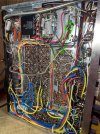
Purchased off CL for a decent price. Replaced the 2SC458 WITH KSC1845’S as recommended. Now able to recieve both AM and FM but is weak. Noted someone apparently attempting to tweak the alignment. Screws that hold the metal cover on tuner gang were missing. While changing the transistors noted the red jumper between the boards had a broken wire. I could not locate this red wire in the schematic, but soldered to point that appeared to be original location. Seemed to be correct, as I used a jumper to the solder joint and worked better.
 

Attachments
  • IMG_4070.jpeg
    IMG_4070.jpeg
    194.7 KB · Views: 21
  • IMG_4090.jpeg
    IMG_4090.jpeg
    134.5 KB · Views: 21
Last edited by a moderator:
Register to hide this ad
Removed your link to the PDF file. A link to a review or ad of it, but something downloads a potentially harmful file. Sorry.

As far as your Oscope, only has a 18Mhz bandpass. Might be ok for audio or IF work. You would be better off with 100 to 200Mhz bandpass. Older CRT based oscope can be had pretty cheap. Not $13, but under a few hundred.
 
Hi,
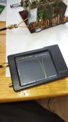
my last toy (but very GOOD toy) for tuner align - NanoVNA H (~40USD on Aliexpress), I used it for re-channel Japan version of Sansui TU-7500 from 76-90 to 88-108 MHz range. With simple loop of wire it work like heterodyne resonance indicator for setting up the OSC circuits and other coils.

1707126978582.jpg
 
Sound Technology made a separate FM transmitter module you connected to the antennae input. And then you used your Sound Technology Distortion analyzer and frequency generator to provide test signals and to measure distortions etc. It was always handy to have a 465 Tektronix Oscilloscope handy. Is how we did it way back when. You also needed a good frequency counter to check the intermediate frequency and to calibrate the 19 KHZ stereo pilot filters.
 
Hi,
my last toy (but very GOOD toy) for tuner align - NanoVNA H (~40USD on Aliexpress), I used it for re-channel Japan version of Sansui TU-7500 from 76-90 to 88-108 MHz range. With simple loop of wire it work like heterodyne resonance indicator for setting up the OSC circuits and other coils.

View attachment 3109328
Hi,
Getting back to this today. Just wanted to follow up on your suggestion. After research, appears I would still need an oscilloscope in conjunction with the NanoVNA H. Am I misunderstanding or are you using the NanoVNA to tune by ear?
 
Removed your link to the PDF file. A link to a review or ad of it, but something downloads a potentially harmful file. Sorry.

As far as your Oscope, only has a 18Mhz bandpass. Might be ok for audio or IF work. You would be better off with 100 to 200Mhz bandpass. Older CRT based oscope can be had pretty cheap. Not $13, but under a few hundred.
Thanks for the advice. Still looking for an affordable O-scope I can justify. I thought I'd update my avatar. Found my original Crystal radio from when I was about 10Yrs old. Left behind the ground rod and 100 ft of antenna wire. :angel: There was no such word as stereo in my vocabulary back then. Upgrading my pic with a before and after. The mono headset is still there.
Does this site have a marketplace? Did not see one. May will go check out the pawn shops today.
 
Thanks for the advice. Still looking for an affordable O-scope I can justify. I thought I'd update my avatar. Found my original Crystal radio from when I was about 10Yrs old. Left behind the ground rod and 100 ft of antenna wire. :angel: There was no such word as stereo in my vocabulary back then. Upgrading my pic with a before and after. The mono headset is still there.
Does this site have a marketplace? Did not see one. May will go check out the pawn shops today.
You have to pay an annual subscription fee to access the Market place.
 
if you only need this for one tuner, you'd get off cheaper just paying someone to do it.

i've got about $2k in used gear so that i can align tuners. granted the scope and distortion analyzer has other uses but the freq. counter and am-fm stereo generator have no other uses.

i'm doing alot of receivers and tuners so i could easily justify the cost.
 
Hi,
my last toy (but very GOOD toy) for tuner align - NanoVNA H (~40USD on Aliexpress), I used it for re-channel Japan version of Sansui TU-7500 from 76-90 to 88-108 MHz range. With simple loop of wire it work like heterodyne resonance indicator for setting up the OSC circuits and other coils.

View attachment 3109328
Hi,
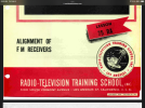
Is this the method you are using without an oscilloscope? Understand I cannot attach a link, so just used a screenshot of the document. I am not so sure if will work for stereo FM receivers. IMG_0194.png
 
@jisake1: not actually, this book describes all the parts of the tuner - Front-end, IF, detector, I use this small gadget fir setup only Front-end. And method is standart for all analog FM-tuner: on first stage you setup the boundaries of the frequency tuning of the generator (OSC), in my case it is from (88-10.7) - (108 -10,7) = 77.3 - 97,3 MHz, I have removed 1 turn from the OSC coil and change cap from 12pF to 5,1pF, then setup low frequency of heterodyne with coil core in 77,3 MHz on my NanoVNA, and high frequency of heterodyne with varicap to 97,3 MHz. After it I setup input LC for range 88-108 MHz (replacing cap from 12 to 10pF) and 2 remaining contours of the mixer replacing 15pF caps to 10pF SMD ;) For setup IF amp and detector I used my NWT tool ("Sweep Generator 0,05 mHz - 40 mHz" on eBay) and Laptop.
 
If you know how to do it by ear, you can easily figure out how to use a cheap FM car adapter for alignments. Put it at least 30 ft. away from the tuner.
They are very good today, using plentiful cheap cell phone technology and timing references. Can be set to any frequency from 88-108, and produce at least 35 dB stereo separation. More important, they are fairly precise in frequency placement - which you need for tuner alignment.
Your RF "level control" is how far away you place it.
The deal is this - you need to know where you are going, to do an FM alignment, with a tool like this. Easy peasy to do a quick check on an old receiver, if you've already experienced 5-10 successful alignments on various models. I posted links here to my discussion of testing 2 of these here not too long ago. Which also had details on the 2 models, and 120V to 12V car lighter jack / power supply to use it at home. They both had bluetooth for audio in, as well as micro usb cards.
I mean, you get a lot for 15 bucks delivered. If you can drive it.
 
Last edited:
Need advice on my Kenwood KR-4140. Recently received my oscilloscope. Not a high dollar scope but appears to meet my needs. Included a link to video in testing the new (to me :)) hardware. Includes the HP 608E signal generator in operation I picked up.

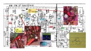

As part of this post, can anyone advise on the current transistors in the IF UNIT (UA1224K)? I replaced all the 2SC458's in the unit. As a result, the AM section works great. Found there's more than an alignment needed for the FM tuner. Very week signal with an antenna. Only have one good station around 88.5.

In the photo attached as schematic, appears the original transistor Qb1 (SE-3001) is not allowing signal to continue down the circuit. Cannot find a best substitute for a (SE3001(W). Additionally Qb2 (SE3001(R) appears to have been changed. Number on this transistor is GE39. Again did not find if this is the correct selection or number to cross. Unsure what the (W) or (R) suggests? I just know the one with (W) has a white paint dot on top. Please review the photo for more details. I confirm I tested on the CB for now, prefer to have a replacement and change at same time. The main concern are the E, B, & C do not agree with the typical Kenwood symbol on board. Not sure if just mislabeled or someone installed wrong?
Is the ME3001 a correct or best selection?
1711718929112.png

Photo in yellow are compliments of another post sent prior. I followed it and AM section works great. Just unclear why the reading say different on the UA1224K?
 

Attachments

  • KR4100_BOARD UA1224k.jpg
    KR4100_BOARD UA1224k.jpg
    125.7 KB · Views: 4
  • Kenwood symbols.JPG
    Kenwood symbols.JPG
    11.4 KB · Views: 4
Last edited:
Back
Top Bottom