• The move to the new server is done. There are some software and database maintenance updates in process. This has us passing the hat around to help out. We appreciate any donations. Seriously, even a dollar helps. The payment page may be found here - https://www.audiokarma.org/support.html

All-Purpose Stereo 5-20 front-end PCB

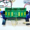
Happy New Year, AK peeps! So, I did a trial run of these boards, and of course upon inspection I found a mistake that I made -- oops! Luckily, it's just a silk screen mistake that I can document as errata in the instructions; the orientation indicator (where the outside foil end of the capacitor should be connected) is backwards for the output coupling caps -- the outside foil end should be connected to the long tail pair tube plates. I'll correct that for the next run! In the mean time, I'm hoping to build one up before the end of the month. Teaser photo attached.
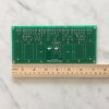
 

Attachments

  • IMG_5037.JPG
    IMG_5037.JPG
    50.6 KB · Views: 31
Decided to populate one of these boards today... this one is destined for an EL84 amp that uses Heathkit AA-100 iron. Flying leads for connections to external constant current sink board (for long tail pairs) and feedback loop. I put TE screw terminals on the other connections, but I may simply end up using flying leads soldered onto those pads all the time, going forward.
 

Attachments

  • IMG_0041.JPG
    IMG_0041.JPG
    70.8 KB · Views: 26
If you ever decide to make a run of an amplifier front end that does not depend on loop NFB, I am in...:) Say a LTP of EL84's for instance...as well as a battery biased DN3545N3/10M45 current reg. Run it in 4 oz Cu, and stick in some solder posts for the connections. There is no need to put traces closer together than what 4 Oz will stand...and the stuff is durable for when things need to get replaced and tuned.
cheers,
Douglas
 
If you ever decide to make a run of an amplifier front end that does not depend on loop NFB, I am in...:) Say a LTP of EL84's for instance...as well as a battery biased DN3545N3/10M45 current reg. Run it in 4 oz Cu, and stick in some solder posts for the connections. There is no need to put traces closer together than what 4 Oz will stand...and the stuff is durable for when things need to get replaced and tuned.
cheers,
Douglas

Of course, nothing is forcing you to use NFB with this one. All this board does is enforce the "gain stage DC-coupled to LTP inverter / driver stage".

(Yes, I use the 10M45s in the tails of my LTPs.)
 
In cascode I hope. I built a lot of them with two depletion-mode MOSFET's, and using the 10M45 on top leaves more room for the FET on the bottom to work in, and with the higher drain-source voltage its gate capacitance is reduced.
cheers,
Douglas
 
Revising this thread after a while...

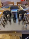
Well, 8 years after getting one of Jason's boards, I have now put it to use in a stereo Mullard 5-20 build! I have been sitting on some suitable toroidal output transformers made in Canterbury UK about 20 years ago by Canterbury Windings. I bought these on a whim because they are specified for Mullard 5-20 amplifiers, so it was a nice surprise when an engineer friend of mine told me recently that he knew (and rates) the designer of these transformers, Terry Monaghan.

The project got stuck when I found that I didn't have a suitable power transformer, and I went back and forth thinking about whether to use tube or solid state rectification. In the end the same friend offered me a huge transformer which pointed clearly to solid state, so I took that route. The resulting voltages are a tad lower, e.g. 392V rather than 433V on the EL34 plates.

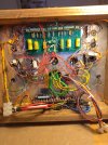
It took me a while to follow the concise instructions for using the All Purpose Stereo 5-20 front end pcb, especially as I was using a pentode EF86 for the gain stage, and I'm still not quite happy with the screen grid supply. I didn't think of revisiting this thread when I was doing the final build, but I'm glad I've found it now as Jason addresses the issue of wanting to use a pentode for the gain stage in post #12 above. Cosmetically, I still have to shorten the extra wires from various primary and secondary taps, as well as the massive ground and heater wires, of the power transformer.

While I haven't quite buttoned up the power supply issues, I'm glad I've had the opportunity to use the board. It is a convenient constructional aid. The amp sounds very good to my ears and there are no problems with the toroidal outputs. The sound is clear rather than 'tubey' and the effect is that I listen to the music rather than to the amplifier.
 

Attachments

  • IMG_20260619_214808.jpg
    IMG_20260619_214808.jpg
    110.1 KB · Views: 26
  • IMG_20260619_214735.jpg
    IMG_20260619_214735.jpg
    197.5 KB · Views: 26
All my push-pull power amps use this basic topology - a gain stage driving a long tail pair driving pentode outputs. However, it's not difficult to wire this configuration point-to-point, and that allows more flexibility regarding parts sizes, footprints and placement. I don't think a PCB has an advantage for tube circuitry except in a manufacuring environment where hundreds of identical units will be produced or components must be densely packed.

Jack
 
Last edited:
All my power amps over 5W or so use this basic topology - a gain stage driving a long tail pair driving push-pull pentodes. However, it's not difficult to wire this configuration point-to-point, and that allows more flexibility regarding parts sizes, footprints and placement. I don't think a PCB has an advantage for tube circuitry except in a manufacuring environment where hundreds of identical units will be produced or components must be densely packed.

Jack
I have built three mono 5-20s and a bunch of 5-10s, all wired point to point, so I hear you on this. This was just my report on using this board many years after I first got it, and years after first reading this thread.

I don't think it would be suitable for a beginner wanting to build a stereo Mullard 5-20 for the first time because the component numbering in the Manual (I used rev. 0.2) and on the board (mine is rev. 1) does not correspond with the original Mullard schematic. This means that while getting to understand the board layout, you have to work with two sets of numbers. I found this surprisingly confusing and I needed to print out a Mullard schematic and then add the board numbering in parallel to avoid confusion. It would be most useful as a tool for people constructing multiple amps using this topology. As we say in the UK, 'horses for courses'.
 
Back
Top Bottom