• The move to the new server is done. There are some software and database maintenance updates in process. This has us passing the hat around to help out. We appreciate any donations. Seriously, even a dollar helps. The payment page may be found here - https://www.audiokarma.org/support.html

Allied 333 (Pioneer SX34) Magic Eye Tube display will not change when tuning

Dcoughlan

New Member
I recently picked up an Allied Knight 333 tube receiver. After some Deoxit on the switches and cleaning of the tube contacts I now have clean audio with FM and AUX input. I have not yet plugged in a turntable, but will soon. The 6E5 Magic-Eye was very dim so I verified the power voltages and convinced myself all were ok and ordered a NOS unit on eBay. The new 6E5 arrived and I installed. The bulb intensity is now very good.

I do however have an issue with lack of the eye display moving when tuning FM. It’s fixed at about 75% on both sides from top to bottom and does not expand/contract as I adjust the tuner.

I have measured the voltage at Pin 3 of the 6E5 when adjusting the tuner and it will only go between 0VDC and -0.9VDC. The research I’ve done online states the voltage should swing closer to -10VDC - is this correct?

I have verified the 1M resistor in the tube connector shell is within the 20% rating as it reads 970K, so I assume not my issue.

I have a few challenges:
  1. My first tube receiver project
  2. Lack of Service Manual
  3. Lack of component orientation - all discrete wired point to point.
  4. Poor quality schematics. - I have both a sketchy copy of an Allied 333 and the Pioneer SX34 - Neither are 100% for what is in the unit I have.
Any ideas on what circuitry I should check first and if possible, pics or schematic markups for location of those parts on the bottom side of the unit?

Thanks in advance.
 
Register to hide this ad
Does this have fresh caps? The originals are well known for failure and honestly as an early troubleshooting step replacing them is pretty much required.
 
Which specific caps? If everything in the receiver functions as it should, which and why would specific caps in the detection circuit be the issue? I’ve never been a fan of shotgunning all electrolytic, without signs of failure. I appreciate your input but would like recommendations for exact components - by circuit. Thanks
 
A few questions…. Does the dim, older magic eye show variations in tuning strength? If so I suspect the new Eye tube, however brighter.
Does either tube work on the AM band?
How close to 242 vdc is the B+ branch that feeds that tube? If you want a starting place for filter cap replacement there’s a 30uF 350v on that circuit.
I’m with Gadget on replacing all the gray coupling caps and all the electrolytics. I would also replace that 1M resistor on the eye tube, if only to rule it out.
 
I'll freely admit that "change a bunch of parts" sounds like a very lazy answer, and in a way it is, but there is reasoning behind it. Lots of empirical evidence of those specific parts aging poorly.

If you want to do this in a very specific manner though, the eye tube will run off the ALC line in the tuner depending on AM or FM. The stronger the signal, the more negative the ALC line swings, which causes the eye to close. There is usually a cap to ground on that line to dump any audio signal but preserve the DC voltage. Its also a very high impedance source, so any leakage will skew things.

If you made me point at a specific individual cap for FM, its this one. Notice its after a 2.2M resistor, so any leakage to ground screws this up. That resistor being open will do it too but if I were a betting man I'd go with the cap over the resistor if its one of those grey oil caps.

1790343805456.png

this is the one for AM that I'd look at.

1790344295795.png
 
Thanks to both for feedback.

RWOOD:

Yes - original dim tube and NOS tube both are fixed and do not change with tuning.

The Eye tube illuminates on both AM and FM - But like FM, the display is fixed.

Pin 1 -millivolts that vary

Pin 2 - 34.9 VDC

Pin 3 - -0.9 VDC

Pin 4 - 204-0 VDC - is this too low?

Pin 5- 1.5 VXDC

Pin 6 - millivolts that vary

On my Allied schematic, there is not a 30 full @ 350V electrolytic

GADGET73:

I will hunt down those specific caps in my unit.

What is a good series of cap to replace the PIO caps?

Thanks again
 
I bypassed Cap C37 0.01u with a replacement - no change to performance
I swapped the 1M resistor in the tube socket - no change to performance.
Also, the 2.2M measured within spec, as did the 100K
 
Have to remove the old cap, not bypass it. The fail mode tends to be DC leakage, so if its still in circuit the leakage path remains. The voltage at pin 3 should vary from around 0 to about -8 volts depending on signal strength. If its hanging at or near zero the eye won't close. The more negative it goes, the more it closes.

Any film cap is honestly fine. I tend to use boring polypropylene caps, axial or radial as you see fit for physical reasons. Illinois MPW, Cornell 940 or 942, Panasonic ECW, etc.
 
To clarify, i removed and replaced with a similar value film cap.

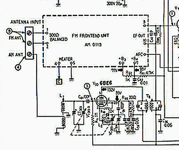
What I did find is a 270K resistor in parallel to ground across the 0.01 cap. As part of this troubleshooting I measured the voltage at pin 2 of the filter T6 in the schem above. It swings between 0.0V and -9.0 on the pin. However on the opposite side of the 2.2M, it drops to the sub -1.0v range. When I remove the 270K, I get as much as -4.5V and the eye fully closes on FM. Between stations the eye only recedes back about 30%.

Not sure why this 270K is in circuit???

Any thoughts on improving the pin 3 voltage beyond this?

Any other thoughts?

AM still as original. I will need to check the area of the AM circuit you noted above.

Thanks
 
Any other thoughts?


Thanks
I Googled this. Maybe it'll help. :idea:

c3485d62-d07b-4f40-b7b9-655dbd6b86e1.jpg

a16eb646-b611-4b0a-8ff7-b37de5fb69fd.jpg
 
hm, there isn't a 270K in the Pioneer schematic, but I suppose there could be a difference on the Allied schematic. 2.2M into 270K is going to significantly alter how much voltage gets to the eye tube grid, which will of course affect how it responds. Unless the circuit is supposed to have a lot more voltage swing than the eye tube wants, I'm not sure why it would have that.

other thought, if they use different eye tubes, the response is different. 6E5 needs a lot less voltage than a 6U5 does.

Possible the tuner gain is poor, that will result in low voltage getting to the eye tube grid as well. Low voltage would do that, may want to see if the plate and screen voltage in the IF strip is reasonable. The IF parts are common so if its not right on AM or FM, guessing its going to be a common factor.
 
7a99e348-c766-4f24-bcbb-07b83382a283.jpg

I found this schematic of the Pioneer SX-34B tuner section. See if it matches your Allied receiver's section.
 
Last edited:
The voltage out of the coupling transformer T6, Pin2 goes as low as -10.VDC. The drop across the 2.2M and the 270K 9Before I took out of circuit) dropped the voltage to sub -1.0VDC. Probably a combination of issues. Per Rwoods post - above - I don’t get 242V on the 6E5. The max is about 205VDC. May need to hunt down this difference.

Thanks
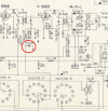
I'd pull one leg of that 1 meg-ohm grid resistor (circled 3-point, on the schematic). Measure it. Hopefully, it's that simple.

If it's off by >20%, I'd replace it with a good metal-oxide resistor.

:thumbsup:
 
Back
Top Bottom