• The move to the new server is done. There are some software and database maintenance updates in process. This has us passing the hat around to help out. We appreciate any donations. Seriously, even a dollar helps. The payment page may be found here - https://www.audiokarma.org/support.html

Altec 1570b Full Restoration but what mods?

Doubert

New Member
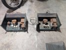
I just acquired and disassembled a set of Altec 1570b's for a full strip/powder coat/silk screen back to original look, while getting rid of all that lovely rust bubbling. These had been spilled on, rode hard and put up wet, but someone managed to save them and keep them safe til now.

Now I am in the deciding on what to mod, getting a parts list together for said mods, and deciding on how to mod these for best meshing with the Altec 612 boxes I built that have Altec 615b coaxial inside the cabinets and Altec 511b horns with Altec 802d drivers on top. Using the 615b LF driver and the 802d as HF with a J.M. designed crossover. I can also swap to the 615b Coax HF with a separate crossover if desired.

I have seen a lot online about Tom Tutay, and as he unfortunately is no longer with us, I come to the community to ask if anyone has any schematics or notes they can share that aren't from the 1997 VTV magazine, or the 2006/2011 notes and schematics to Ken that they would be willing to share here/dm's or point me in the direction of.

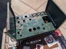
I'm really excited to bring these to life again and am requesting any advice or information people are willing to share. As a disclaimer, I do know that 920V is no joke and have lots of experience working with electricity at high amperages/voltages, just not with tube amps. Picture below of how they came to me.PXL_20261006_152741085.jpg
 

Attachments

  • PXL_20261006_223212841.jpg
    PXL_20261006_223212841.jpg
    143.4 KB · Views: 27
  • 5c470db1-5ff4-4b87-934c-5c964f04522e.jpg
    5c470db1-5ff4-4b87-934c-5c964f04522e.jpg
    169.2 KB · Views: 25
  • PXL_20261006_220900955.jpg
    PXL_20261006_220900955.jpg
    100.8 KB · Views: 20
  • PXL_20261006_175822675.jpg
    PXL_20261006_175822675.jpg
    154.3 KB · Views: 22
Register to hide this ad
Will watch with interest, :lurk: I have quite a few of these that I have not yet touched. Thankfully in better shape than those you have but would be interested in any mods.

I only recapped mine, and the changes I did were personal cosmetic ones, removing the divider wall, relocating the big wire wound resister to under the chassis, and then replacing the front metal cover with a clear plexiglass one and retaining the cage.

I have a different pair and was thinking of redoing that one by removing the sides and leaving everything open, I will remove the safety switch and just bypass it. I am not worried about someone messing around and getting shocked as no one will be using them other than me and no kids in the household, they all moved on.
 
I've seen a few threads with yours in them! I'll be sure to post here as it goes along. They are getting dropped off on the 23rd for their cosmetic re-finishing. I'm definitely going to be doing the Tom Tutay mods, just trying to find more recent versions of said mods. I've started putting together parts lists based on the various schematics I have found but still searching for more information before I can have a final parts list and schematic. Which I'll be sure to share here as well.
 
I also have stacks of the 1569's, not sure of what I want to do with those. I have moved from wanting things in racks. I still have full size Middle Atlantic rack cabinets from when I was into SAE, and Phase Linear, they have been sitting for years unused in spare rooms. I used to drool over that one guys site where he collected all those SAE gear and had them in racks, so I kind of recreated that in my own system. I do have some of the SAE X amps, they are class A amps, that I would like to service they are kind of unique.
 
Love that SAE gear, I've got a set of Daniel Electronic Gold Pentode #130 KT88 monoblocks currently as my main amps. I've got a buddy that runs some SAE gear though and it all sounds lovely.
 
Potentially OT but have you considered running the speakers 3-way, with the 605b tweeters as HF and the 802 as mid?
I have thought about it, it's definitely a crossover I want to try out but I am not much of a crossover designer. I would build it if I could figure out what I need to build but I recently got an Otari MX-55 and these 1570b's so I have two projects to finish before that one starts.
 
compressed pdf
I've got the 1997 VTV schematic already but thanks for uploading it! Did you do the mods exactly as the schematic is written or did you change anything? I'm looking at changing the 6X5 tube rectification out for solid state rectification instead. As well as having to find an octal delay and bridge rectifiers that are still available in 2026.
 
something that has long bothered me about many modifications like this is they lack explanation of why the change is being made and exactly what it does. I'm not a purist but I want to understand the thinking.
 
something that has long bothered me about many modifications like this is they lack explanation of why the change is being made and exactly what it does. I'm not a purist but I want to understand the thinking.
I recommend looking into Williamson Tube Amps as a starting point and understanding the different circuits that designers are using to modify the various parts of the amp and how they do what they do. I personally prefer diode rectification over tube rectification which is why I am going to be changing up the 6X5 bit of the circuit. As Tom Tutay is no longer with us, I can't ask him for why he made specific choices or how they changed from 1997 to the last one that he built. A lot of the mods on this specific amplifier are to make it so your under 70hz signal isn't cut off at the knees as it is in the original 1570b design.
 
The diodes vs the 5R4 I get, but none of the rest of that appears that it would do anything for frequency response, so again I'd like specific reasoning for each piece of the puzzle. I find enjoyment in understanding things, not just following the directions.

just my interpretation on it though

1&2 - higher voltage, less sag, restore the delay that the tubes provide.

3 - filter choke on negative side of supply - why? Nothing feeds from here.

4 - separate power transformer - assuming this is related to the EL34 change, stock transformer would otherwise be overloaded?

5 - 12ax7 for 6072 (12AY7) - 1/3 the gain, less Miller effect I suppose but it will significantly affect the amount of open loop gain

6 - 6sn7 tail resistor - looks like 2.2K on the schematic, not really enough to serve as a proper diff amp. Maybe some local feedback and self-correction to improve balance of the inverter?

7 - 6W6 for EL34 - no idea. Are we trying to make more drive power for some reason?

8 - fuses, test points, bias adjustment - basic sanity updates

9 - re-cap - also basic sanity

10 - 75K plate resistors - incompletely explained but these are different values for the 6SN7 stage, probably partly to account for the tail resistor, but also likely biases it into a more linear range. It also reduces gain of this stage a bit more.

11 - matched 47K at V1 - this is what sets inverter balance, standard procedure for a split load inverter. This is also a value change, which is not specifically mentioned but probably because of the different tube type

12 - resistor upgrade - also sanity, old are probably noisy and off-value

There are other value changes not specifically called out which makes this all a lot more difficult to pull off without very careful study of the schematics. Again part of why I don't like such lists, but it would have much lower open loop gain. I see the feedback resistor is smaller which would increase feedback as well. This should need a fair bit more signal to drive to full output power as a result. An explanation from the guy who came up with this would help. Not owning a Ouija board I get that its not happening now but this was published nearly 30 years ago, they certainly could have explained it then.


The 6X5 that is not specifically mentioned on that list but is in the schematic is providing a delay for the front end tubes. Replacing it with silicon would eliminate that and probably cause some weird noises on startup. I'd leave that in place, or sub it for a damper diode in series with the output of the silicon to maintain the delay.
 
I recommend looking into Williamson Tube Amps as a starting point and understanding the different circuits that designers are using to modify the various parts of the amp and how they do what they do. I personally prefer diode rectification over tube rectification which is why I am going to be changing up the 6X5 bit of the circuit. As Tom Tutay is no longer with us, I can't ask him for why he made specific choices or how they changed from 1997 to the last one that he built. A lot of the mods on this specific amplifier are to make it so your under 70hz signal isn't cut off at the knees as it is in the original 1570b design.

What exactly is it with the original design that cuts off the low end response. Plus I am unsure as to the amps ablity on the other end of the spectrum, what is the upper ends limits.

When and if I learn how to use test gear I would love to measure to performance of these amps.
 
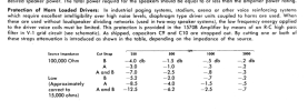
the most obvious frequency limiter is right at the input, but also the easiest to remove.

1791742250988.png

With the jumpers at A and B in place that goes away.

1791742394374.png

thats what it looks like if you cut one or both jumpers, and what effect source impedance has on that.

its not mentioned but the position of that level control will affect HF performance. It will be best with it turned all the way up, otherwise the Miller capacitence in the tube plus the resistance of the pot forms a low pass filter.

nothing else in here is any sort of obvious frequency limiter, which probably means the transformer(s) are the limiting factor. Most likely the output, trying to get full range at 170 watts is a heck of a task. That response is probably quite a lot better if not pushed to it's power limits.
 
3 - filter choke on negative side of supply - why? Nothing feeds from here.
Looks like in a HV supply that this would keep the voltage to the core down for insulation issues. Chokes generally have a max voltage spec. Works the same as in the plus lead. I've seen this in some old organ schematics.
 
Back
Top Bottom