

I received one of these amps and could find very little info on them so I figured I would make a thread about the minor repairs I need to do to mine and collect some info into a single spot for it. It seems that the 351A and B models are very similar and I was able to find a schematic for the "A" variant. If it's the full schematic then the "A" variant does not include the protection circuit that the "B" variant has. Both A and B are point to point wired and use germanium transistors throughout including six Bendix B1272 TO-3 case transistors, four of which are the outputs. The "C" variant that came later uses silicone and PCBs and has an entirely different layout and front panel graphic.
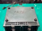
Mine is serial number 1698 with date code 391420 which I think means that it was made in the 20th week of 1964.
The germanium transistors all tested good (Phew! Replacements are hard to come by).
This one was drawing an amp of current at idle and getting hot. Not sure what bias is supposed to be but across each of the emitter resistors (1 ohm, and there's four of them located on the top in the back connected to the protection circuit switch) I was seeing 0.4V!
It worked fine but as it heated up more and more it slowly started slurping more current until it hit 2A at idle and I turned it off.
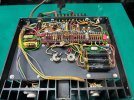
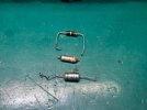
Found R16 in the bottom of the unit (33 ohm 2W carbon comp) to be open and looking quite dark. Replaced with a 3W 33ohm carbon comp and the bias dropped down to 90mV across the emitters. I'm not an expert at this but from my experience working on silicone amps, that would be quite high. This amp however, seems very happy at 90mV (any ideas you can add would be helpful as there is pretty much zero info online about these) and barely draws any current. The bias adjustment trimmer didn't do a ton with it ranging from 80-120mV when adjusted and the amplifier is working great and all voltages look normal. I checked every other resistor and all of them tested within 5-13% of spec so I left them alone. There is no noticeable crossover distortion that I can see so it doesn't seem to be negatively affecting the sound.
On the capacitor front, C1, the input coupling cap was leaking and bloated and measured at 9uF when it should be 5uF. I replaced it with a 4.7uF 50V WIMA film cap (measured at 4.8uF which is well within the typical 20% tolerance of electrolytic caps).
C2 (25uF 25V) was also looking a bit unhappy so I measured it out of circuit and it was 49uF! I then noticed that Altec specced a 25V cap into a part of the circuit that sees 34-37V which explains things.
I adjusted the center voltage to get the highest output power without clipping which is around 22V on the right side outputs.
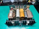
I did some disassembly and cleaned it as best I could. Cleaned and lubricated the level pot, new mica and thermal paste on the outputs, and removed some corrosion from the screws, transistors, and sockets that was causing intermittent voltage at one of the output transistors.
Final measurements: it puts out 17Vrms into 8 ohms at 1KHz or 36wpc. It's rated for 18Vrms but altec says that they took those measurements at 128VAC line input and I'm at 124 ish. It's been running for a few hours and is still cold to the touch. It seems to sound really sweet. This is my first germanium transistor amp. I'm going to sell it but once again...though that sharing this info might be helpful for others in the future!
I've attached the 351A schematic with some notes on what I found wrong.
Mine is serial number 1698 with date code 391420 which I think means that it was made in the 20th week of 1964.
The germanium transistors all tested good (Phew! Replacements are hard to come by).
This one was drawing an amp of current at idle and getting hot. Not sure what bias is supposed to be but across each of the emitter resistors (1 ohm, and there's four of them located on the top in the back connected to the protection circuit switch) I was seeing 0.4V!
It worked fine but as it heated up more and more it slowly started slurping more current until it hit 2A at idle and I turned it off.
Found R16 in the bottom of the unit (33 ohm 2W carbon comp) to be open and looking quite dark. Replaced with a 3W 33ohm carbon comp and the bias dropped down to 90mV across the emitters. I'm not an expert at this but from my experience working on silicone amps, that would be quite high. This amp however, seems very happy at 90mV (any ideas you can add would be helpful as there is pretty much zero info online about these) and barely draws any current. The bias adjustment trimmer didn't do a ton with it ranging from 80-120mV when adjusted and the amplifier is working great and all voltages look normal. I checked every other resistor and all of them tested within 5-13% of spec so I left them alone. There is no noticeable crossover distortion that I can see so it doesn't seem to be negatively affecting the sound.
On the capacitor front, C1, the input coupling cap was leaking and bloated and measured at 9uF when it should be 5uF. I replaced it with a 4.7uF 50V WIMA film cap (measured at 4.8uF which is well within the typical 20% tolerance of electrolytic caps).
C2 (25uF 25V) was also looking a bit unhappy so I measured it out of circuit and it was 49uF! I then noticed that Altec specced a 25V cap into a part of the circuit that sees 34-37V which explains things.
I adjusted the center voltage to get the highest output power without clipping which is around 22V on the right side outputs.
I did some disassembly and cleaned it as best I could. Cleaned and lubricated the level pot, new mica and thermal paste on the outputs, and removed some corrosion from the screws, transistors, and sockets that was causing intermittent voltage at one of the output transistors.
Final measurements: it puts out 17Vrms into 8 ohms at 1KHz or 36wpc. It's rated for 18Vrms but altec says that they took those measurements at 128VAC line input and I'm at 124 ish. It's been running for a few hours and is still cold to the touch. It seems to sound really sweet. This is my first germanium transistor amp. I'm going to sell it but once again...though that sharing this info might be helpful for others in the future!
I've attached the 351A schematic with some notes on what I found wrong.
Attachments
-
351A schematic.pdf283.8 KB · Views: 3
-
 Stock bottom w bias and center voltage.jpeg167.5 KB · Views: 8
 -
 Parts I replaced.jpeg153.4 KB · Views: 6
 -
 Bad parts.jpeg105.6 KB · Views: 6
 -
 IMG_4062.jpeg116.2 KB · Views: 6
 -
 IMG_4066.jpeg89.5 KB · Views: 6
 -
 IMG_4069.jpeg104 KB · Views: 6
 -
 IMG_4071.jpeg105.8 KB · Views: 8
 -
 IMG_4074.jpeg104.4 KB · Views: 8

