• The move to the new server is done. There are some software and database maintenance updates in process. This has us passing the hat around to help out. We appreciate any donations. Seriously, even a dollar helps. The payment page may be found here - https://www.audiokarma.org/support.html

Altec 605 8ohm/8ohm Crossover recommendations

19Brendan80

AK Subscriber
Subscriber
Well, I usually only post when I'm in too deep over my head and need help from those smarter than me and now seems to be the time. To give a little background, I have recently reconed a couple Altec 615's and turned them into essentially 605's. The only differences being the cone I used is lighter than the typical 604 cone traditionally used because I figured it would work better with the reduced magnet gauss of the 605/615. You may remember I am also using these on a couple of Stromberg-Carlsons. The rest of the parts are all genuine Altec replacement parts. (8ohm woofer coil and 8 ohm diaphragm and proper spider and the surround is still cloth).

This brings me now to picking out a crossover to build. I see that there are Werner Jagusch on ebay for the 604-8G for about $1000.00 but this is too rich for my blood. I see Great Plains also has a crossover at $240.00 a pop. Looking at the components on there, I cannot justify that amount for money. I can build the Markwart crossovers myself for less than the cost of one from great plains but need a proper schematic for the 605 with 8 ohm drivers.

The Jeff Markwart crossovers seem to be very popular, but I have found multiple different schematics, each with different component values. I know there are 605 schematics, but they won't work properly because of my 605's having an 8ohm load. This leaves me with his:

Simplified Altec 604-8H schematic, or
Simplified Altec 604-8G schematic, which I think?? might work because that model also has an Alnico magnet... but has no phase correction and I don't think Mid frequency EQ.
and the
Phase corrected Altec 604-8H with mid frequency EQ.

Ideally, I would like to have the phase corrected with mid freq EQ but am pretty sure that wouldn't work with my drivers seeing that there were different values noted for the simplified 8H to 8G.

Would the values of the Phase corrected Altec 604-8H with mid frequency EQ be able to be changed to accommodate the 8 ohm loads? Does anyone know what they would be changed to? I know nothing about crossover design but can read a schematic and build anything. If no one was able to come up with a component value change would the simplified 8G schematic work for me? Any help would be appreciated. Thanks.
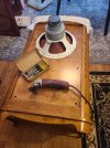
 

Attachments

  • 20231124_104840.jpg
    20231124_104840.jpg
    138.6 KB · Views: 47
  • 20231124_151336.jpg
    20231124_151336.jpg
    128.7 KB · Views: 124
  • 20231124_171150.jpg
    20231124_171150.jpg
    152.3 KB · Views: 47
Register to hide this ad
I think you'd be best off contacting Jeff Markwart directly for his opinion ( his contact info is posted at the GPA website ).

His best guess will be better than anyone elses.

My guess is that some form of modified N1500 would be the best way forward.

:)

BTW, unless GPA was involved in supplying parts to you here >> then you're at a real disadvantage in getting something to work properly.

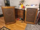
Also, gorgeous cabinets.

index.php
 
Thanks for the reply, Earl, I have reached out to Jeff and currently corresponding with him. Electrically they are the same as any other 8ohm Altec as they use Altec replacement parts. Thanks for the compliment on the cabinets, but I can't take the credit there. They were built for me in China and shipped to the U.S. I did have to modify them to front mount the Altecs though.
 
@19Brendan80

I'll eventually post a schematic for you to try out if you want ( it's a modified N1500a using a few scavenged .frd + .zma files from 8ohm Altec drivers owned by others ).

Since you're dealing with your own unique Franken-Duplex, anything posted ( by me or Jeff ) is going to require a little bit of part swapping for best results ( your custom woofer-cone tosses the woofer response into the deep-blue sea of the unknown ).

:)
 
Last edited:
What about volume…?

Does the 8ohm driver set up need a different cab vs. a 16 ohm 605…? Or port size…?

Hmm, now that I look again where is the port…?
 
I think you'd be best off contacting Jeff Markwart directly for his opinion ( his contact info is posted at the GPA website ).

His best guess will be better than anyone elses.

My guess is that some form of modified N1500 would be the best way forward.

:)

BTW, unless GPA was involved in supplying parts to you here >> then you're at a real disadvantage in getting something to work properly.

Also, gorgeous cabinets.

index.php
I'd appreciate that. Jeff Markwart he recommended a 2nd order Butterworth which I believe is like his 605 schematics but i would need to tweak the values for the 8 ohm load. I'm hoping he gives me an idea of what to change the values to. If you gave me some schematics at some point i could also try those to see which crossover i liked the best.
 
What about volume…?

Does the 8ohm driver set up need a different cab vs. a 16 ohm 605…? Or port size…?

Hmm, now that I look again where is the port…?

Box Volume ( and type, such as Sealed or Bass Reflex ) is driven by the woofers Ts Parameters ( not the voice-coil impedance ).

:)
 
Where is the port…?

I’ve always wondered how that effects bass…front vs bottom, side, etc

Box Volume ( and type, such as Sealed or Bass Reflex ) is driven by the woofers Ts Parameters


which was changed…
 
Jeff Markwart is a helpful guy. I asked him to help me with changing 32343 crossovers to values for 16 ohm drivers a while back. He told me what to do and I built those crossovers recently. They sound great.

But I was glad I posted the schematics on here before I built them. EarlK caught a mistake I made when I copied down what Mark had sent me. It saved me from putting the wrong size coil in.
 
Maybe rear ported?

Have you tried sweeping them with Dats to see what effect those cones have on the Ts specs?
 
I'd appreciate that. Jeff Markwart he recommended a 2nd order Butterworth which I believe is like his 605 schematics but i would need to tweak the values for the 8 ohm load. I'm hoping he gives me an idea of what to change the values to. If you gave me some schematics at some point i could also try those to see which crossover i liked the best.
@19Brendan80

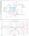
Here ya go ( remember, the N1500a is a Series type crossover );

This is a quite affordable network > due to the relative small values of the LC parts.

Black and Green traces show the filtered LF & HF responses.

Red is the raw response of the woofer file that I used ( from someone's 604-8K ).

Aqua-Blue shows the predicted response around the crossover area ( keep-in-mind, this is all pure science-fiction because these aren't your drivers measurements being used ).
- For instance, I've married the FR of an Altec 20275 diaphragm with the impedance of a 21957 diaphragm. Sketchy?? Yes, but at least they're from the same era.

Altec modified- N1500a for Franken-605.png

- "Z" off-set was set as 4.25". This info comes from JeffM as the measured distance between the 2 drivers Acoustic Centers ( when measured at 1500hz ).
- Since one can see these traces ( black & green ) are crossing closer to 2K > the 4.25" figure is only pretty-good for my design purposes.

- Yes, that's a 16ohm variable Lpad ( represented here by R9 +R11 >> since that's what seems to work best vs an 8ohm type ).

- The woofers impedance correction circuit ( called a Zobel ) consisting of C4 & R6 can just about be omitted ( especially, if your custom woofer is less "peaky" above 1K when compared to what I used ). If your custom woofers response has more HF than what I've shown, then that'll corrupt the curve somewhat ( around crossover ) and it'll be necessary to pull the peak down some ( start by reducing R6 from 30 ohms to 20 ohms & the 6.8uF cap can migrate towards being 10uF ).

- The HF circuit assumes the use of the drivers loading-cap ( plus regular back-cap ).
- If the loading-cap is omitted ( and you're not using an Altec diaphragm ) then you'll most likely need to reduce the value of C1 somewhat ( how much is up to you dependent on what you see//hear from your own measurements//listening sessions ).

- L3 is optional ( it helps extend the HF drivers response above 10K a little bit > maybe your diaphragm won't need this help >> who knows ?? ).
- If used, it can be the smallest air-coil inductor that you can find >> with the highest DCR value ( iow , the cheapest ).

- I'd use a modern motor-run ( MPP in oil ) capacitor for the 16uF value seen here. ( 16uF >> one can parallel a 1uF cap to a 15uF motor-run if that's all you can find ).

:)

EDIT #1: Here's a very affordable 15uF motor-run.

15uF CDE motor-run at Surplus Center

EDIT #2: Just use the 15uF value for C2. ( I just looked again at the network modeler and the differences in response between the two values is negligible ).
 
Last edited:
What about volume…?

Does the 8ohm driver set up need a different cab vs. a 16 ohm 605…? Or port size…?

Hmm, now that I look again where is the port…?
It's an 8 cu ft. Cabinet... ports on the sides like the Tannoy Canterbury. Cabinet port tuning should rely on the Thiele small parameters of the speaker which are adjustable later. The crossover tuning will be separate from any of those parameters.
 
Thanks for the reply, Earl, I have reached out to Jeff and currently corresponding with him. Electrically they are the same as any other 8ohm Altec as they use Altec replacement parts. Thanks for the compliment on the cabinets, but I can't take the credit there. They were built for me in China and shipped to the U.S. I did have to modify them to front mount the Altecs though.
Gosh, who made the cabinets? Very nice! I have some original 605B that I will have to recap eventually. A future project! I'll be following your thread!
 
Gosh, who made the cabinets? Very nice! I have some original 605B that I will have to recap eventually. A future project! I'll be following your thread!
For the regular 605... jeff has two crossovers: one with mid frequency eq and one without. They both have different values depending on if you're using the original aluminum wire wound diaphragms or the newer style copper wound coils. This is assuming they're 16 ohm as they should be.
 
@19Brendan80

Here ya go ( remember, the N1500a is a Series type crossover );

This is a quite affordable network > due to the relative small values of the LC parts.

Black and Green traces show the filtered LF & HF responses.

Red is the raw response of the woofer file that I used ( from someone's 604-8K ).

Aqua-Blue shows the predicted response around the crossover area ( keep-in-mind, this is all pure science-fiction because these aren't your drivers measurements being used ).
- For instance, I've married the FR of an Altec 20275 diaphragm with the impedance of a 21957 diaphragm. Sketchy?? Yes, but at least they're from the same era.

View attachment 3049210

- "Z" off-set was set as 4.25". This info comes from JeffM as the measured distance between the 2 drivers Acoustic Centers ( when measured at 1500hz ).
- Since one can see these traces ( black & green ) are crossing closer to 2K > the 4.25" figure is only pretty-good for my design purposes.

- Yes, that's a 16ohm variable Lpad ( represented here by R9 +R11 >> since that's what seems to work best vs an 8ohm type ).

- The woofers impedance correction circuit ( called a Zobel ) consisting of C4 & R6 can just about be omitted ( especially, if your custom woofer is less "peaky" above 1K when compared to what I used ). If your custom woofers response has more HF than what I've shown, then that'll corrupt the curve somewhat ( around crossover ) and it'll be necessary to pull the peak down some ( start by reducing R6 from 30 ohms to 20 ohms & the 6.8uF cap can migrate towards being 10uF ).

- The HF circuit assumes the use of the drivers loading-cap ( plus regular back-cap ).
- If the loading-cap is omitted ( and you're not using an Altec diaphragm ) then you'll most likely need to reduce the value of C1 somewhat ( how much is up to you dependent on what you see//hear from your own measurements//listening sessions ).

- L3 is optional ( it helps extend the HF drivers response above 10K a little bit > maybe your diaphragm won't need this help >> who knows ?? ).
- If used, it can be the smallest air-coil inductor that you can find >> with the highest DCR value ( iow , the cheapest ).

- I'd use a modern motor-run ( MPP in oil ) capacitor for the 16uF value seen here. ( 16uF >> one can parallel a 1uF cap to a 15uF motor-run if that's all you can find ).

:)

EDIT #1: Here's a very affordable 15uF motor-run.

15uF CDE motor-run at Surplus Center

EDIT #2: Just use the 15uF value for C2. ( I just looked again at the network modeler and the differences in response between the two values is negligible ).
Thank you earl for this detailed response! I appreciate it immensely. This is going to be a lot for me to sort through, but i should be able to come up with something with all your help. There are lots of options you've given me depending upon my drivers. I assume it would be immensely helpful if i had plots of my drivers responses? I will attempt to get those in another month or so. I'm short on money until after Christmas but will eventually get the dayton dats v3 to test the drivers and plot the response curves which should be even more helpful. I didn't really think that it would be this in depth to create a crossover but now understand there's a lot of unseen information that's needed to do it correctly. You've at least given me a great starting point here. Thank you so much.
 
For the regular 605... jeff has two crossovers: one with mid frequency eq and one without. They both have different values depending on if you're using the original aluminum wire wound diaphragms or the newer style copper wound coils. This is assuming they're 16 ohm as they should be.
I used the one without on my 605b build. So far so good…

IMG_0431.jpeg
 
Last edited:
@19Brendan80

In the absence of more info from Jeff Markwart, here's a parallel-type crossover for you to consider.

Altec modified-Markwart for 8-ohm Franken-605_modB.png

It has quite good Phase-Tracking ( a-la-Markwart ) >> tighter than the modified N1500a which I posted yesterday.
- You can follow the predicted Phase-Tracking by looking at the red + black dotted lines around the crossover region.

Consider this network a worthwhile starting point.

Which sort of capacitor you decide to use is certainly up to you >> but if you're interested in using any modern motor-runs, then the same outfit that I linked you to earlier also has a G.E. ( 27-series ) 9uF capacitor ( that would just need 1uF added in parallel to it to bring it up to 10uF ) . Since this network uses 4x 10uF caps, the low pricing ( for 6 large capacitors ) might make it worthwhile to include a second parts supplier ( in addition to Parts Express, I'll assume ).

- 9uF Motor-Run

- A portion of an 8-ohm variable LPad is used within the EQing circuit ( by connecting tabs 2 +1, in accordance to the displayed circuit ) .

- I wouldn't waste good money on expensive parts until you know ( whatever//whichever ) crossover "floats-your-boat" ( so-to-speak ).

- IOW, simply buy Dayton labelled caps, coils and resistors ( apart from the recommended Motor-Run capacitors ) for your assessments.

Dayton Resistors
Selected Capacitors
2x 2.5mH Dayton Laminated Iron-Core Inductors
1x 1.0 mH Dayton Air-Core Inductor

:)
 
Last edited:
Back
Top Bottom