• The move to the new server is done. There are some software and database maintenance updates in process. This has us passing the hat around to help out. We appreciate any donations. Seriously, even a dollar helps. The payment page may be found here - https://www.audiokarma.org/support.html

Altec Polarity question

onlysleeping

Active Member
I have a set of Altec Magnificent speakers. 802d, 416a woofer, N-500-G crossover.

I noticed that one of the connections to the horn has the positive cable on the left connector, but the other was reversed. From what I have read, it seems like Altec would have polarity reversed between the woofer and the horn, but I'm not sure why one horn would have it reversed from the other. Any ideas?

I am having the crossovers recapped and I wasn't sure if I should set them up the way they were or normal.
 
Register to hide this ad
I covered the same discussion with my Altec Magnificents. Or possibly a proper horn phasing post. I have asked that in the past because I noticed differences in wiring in the same model speakers. I believe the N-500 XO has a wiring diagram with a special note on the bottom about the A500II. I started using a speaker phase phone app to double check. Here was my post. Please post some pics of the Magnificents. Fever

https://audiokarma.org/forums/index.php?threads/out-of-phase-horns-have-you-checked-yours.580598/
 
Last edited:
Someone opened it and forgot to connect it correctly ?
Possibly a new diaphragm ?
I don't think there is enough room to cross the polarity of the diaphragm internally ?

Which ever way you go, polarity wise,
both have to be the same.
 
I don't think there is enough room to cross the polarity of the diaphragm internally ?
Certainly there is, particularly if the position of the cover has been rotated.

Got a compass? Check the magnetic polarity and see if they are the same.
This is particularly important if the driver has been serviced at some point.

Re-gaussing a driver first involves de-gaussing which requires the magnetizer be operated in polarity reverse of the magnetic charge. Human error happens, uncommon but sometimes the operator may forget to switch the polarity of the magnetizer/gausser back to the forward polarity and a driver will end up getting zapped in reverse polarity. The solution when this happens is simply reversing the voice coil lead polarity.
 
I have a JBL 2241H that has reversed magnetic polarity from the factory (i.e., + on red makes cone pop out instead of in like it should), so caca occurs. At first I thought someone wired the plug reversed but I confirmed with a compass that it is in fact different than my others that all pop in.
 
Instead of a compass can I use a dowsing stick?

Sorry but it never occurred to me that I could pull out my compass to check polarity on my driver.
 
Instead of a compass can I use a dowsing stick?

Sorry but it never occurred to me that I could pull out my compass to check polarity on my driver.
In this particular case polarity is used in reference to the direction of magnetic charge, not the electrical polarity of the voice coil.
 
Is there a guide on how to use a compass to check polarity?

Which phone app did you use for checking?

I am currently having the crossovers recapped. Are there any suggestions for new or improved xos?

I also plan to replace the speaker bindings. Any suggestions there?

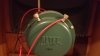
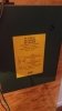
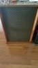
As requested some pics!

20190701_221018.jpg 20190701_221041.jpg 20190701_221032.jpg 20190707_135756.jpg
 
No guide and not a phone app. Use one of these things and hold it flat either in front or behind the speaker/driver and observe the needle. Now do it for the other(s) and see if the needle points the same way, or 180 degrees opposite. If it is opposite, you will need to reverse the electrical polarity on that speaker/driver to get the cone to move the same way when fed the same signal as the other speakers/drivers.

GloCompass_Flat_2015-10-22.jpg
 
The confusion is from the wiring diagram itself. The bottom of the label mentions NOTE: See System instructions sheet for correct phasing connections. I believe the sheet shows the correct phasing for the A500II as being opposite from the label. Maybe someone has the sheet handy for grins
 
I got the crossovers back today with new capacitors.

Before I took everything part, I took pictures and made notes.
Prior to recap, here is how things were set up.
Left speaker:
Left jack - positive cable to amp
Right jack - negative cable to amp
Negative speaker cable connected to the back of the crossover.
Positive speaker cable connected to the front of the crossover.
Black cable on the left of the horn
Red cable on the right of the horn
Green cable on left of the woofer (marked with a +)
Black cable on the right of the woofer.

Right speaker:
Left jack - positive cable to amp
Right jack - negative cable to amp
Negative speaker cable connected to front of crossover.
Positive speaker cable connected to front of the crossover.
Red cable on the left of the horn.
Black cable on the right of the horn.
Green cable on left of the woofer (marked with a +)
Black cable on the right of the woofer.

I bought a compass and compared the woofers and horns.
Both seemed to be in phase with each other, meaning the needle pointed the same way on both components in both speakers.

Since the above wiring seemed wrong, I put everything back as follows in both speakers. I figured since the polarity of the components seems to match according to the compass, make the wiring match too.
Left jack - positive cable to amp
Right jack - negative cable to amp
Negative speaker cable connected to the back of the crossover.
Positive speaker cable connected to the front of the crossover.
Black cable on the left of the horn
Red cable on the right of the horn
Green cable on left of the woofer (marked with a +)
Black cable on the right of the woofer.

Does that seem right? I am listening to stuff now, and it seems a bit bass shy.
 
In addition to the compass, you should confirm that both woofers pop in the same direction with a 1.5 volt battery on the terminals.
 
I went back to the original wiring, since it seemed odd I needed to reverse polarity at the amp. It is odd. One of the issues I have is not knowing which terminal is positive and negative on the crossover to speaker jack connection. From looking at my pictures before I removed everything, I noticed that the black and white cables were different between the two speakers. When I originally set everything back up after the rebuild, I had each speaker 'match' how they were connected. I went back to the original setup - things sound fine. It just doesn't make sense since the compass showed polarity the same between the speakers. Maybe some trickery is occuring in the crossover?

I know I can use a battery to test the woofer for positive/negative, but how do I go about testing the diaphragm / horn?
 
I know I can use a battery to test the woofer for positive/negative, but how do I go about testing the diaphragm / horn?

Use a Real Time Analyzer and look for differences in the spectrum when both components are connected to the crossover.
 
If you play pink noise thru your system and stand 4 to 5 ft in front of the speaker with one turned toward the center line of the horn and then move your head down to the center line of the woofer. The speakers system that is wired correctly the sound spectrum level will remain fair ly constant. The one that is wired out of phase the mid range tones from about 400 to 1200 hz will come and go as you move your head up and down..
 
I went back to the original wiring, since it seemed odd I needed to reverse polarity at the amp. It is odd. One of the issues I have is not knowing which terminal is positive and negative on the crossover to speaker jack connection. From looking at my pictures before I removed everything, I noticed that the black and white cables were different between the two speakers. When I originally set everything back up after the rebuild, I had each speaker 'match' how they were connected. I went back to the original setup - things sound fine. It just doesn't make sense since the compass showed polarity the same between the speakers. Maybe some trickery is occuring in the crossover?

I know I can use a battery to test the woofer for positive/negative, but how do I go about testing the diaphragm / horn?

An old and simple visual trick is to take a narrow strip of separated bathroom tissue, and in a no air movement(still) environment drape with a piece of tape holding in place in front of the horn/s mouth opening. Then pulse the speaker cabinet`s terminals with a battery, noting the polarity of the battery to match the polarity of the speaker post connections.
Observe movement of tissue paper while pulsing with battery, you might need someone helping observe, or doing the momentary connection with the battery..
The thinner the tissue paper strip, the better the motion, plus the lack of any air movement in the room your doing this is important, so the tissue strip is not disturbed except by the intended test`s diaphragm`s air motion wave front.
In the past, I sometimes needed to use a nine volt battery for more movement of the HF/MF horn diaphragms for more conclusive results.
It was always easier to test with the driver raw facing up on a table with the tissue paper laying across the driver`s throat, and with no crossover effecting it a 1.5 volt AA/AAA cell was enough to achieve visible conformation of polarity.

Just a suggestive thought.
 
Back
Top Bottom