• The move to the new server is done. There are some software and database maintenance updates in process. This has us passing the hat around to help out. We appreciate any donations. Seriously, even a dollar helps. The payment page may be found here - https://www.audiokarma.org/support.html

AM-FM Stereo Multiplex Receiver KW-44

Hi everyone
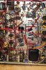
i need help with my tube gear .i have Kenwood KW-44 Receiver i recap all capacitors it working and sound very good .the problem if i turn it on for around 30 minute it will BLOW one of the preamp tube 12AX7 .and then will sound so ugly .i need help to fix it and i do not have any diagram and it very hard to get info from the wep .
can any body help with service manual or schematic to fix it
thanks
Ali
 

Attachments

  • IMG_0861.JPG
    IMG_0861.JPG
    58.8 KB · Views: 38
  • IMG_0863.JPG
    IMG_0863.JPG
    79.1 KB · Views: 38
  • IMG_0869.JPG
    IMG_0869.JPG
    91.5 KB · Views: 39
Register to hide this ad
Does this use the 12ax7 tubes as cathode resistors? If so, what you may be experiencing is too much current in the output stage for some reason, which causes excessive heater voltage on the 12ax7. You may need to trace the heater wiring on the tube that fails to see if it connects to the rest of the heater circuit or if it connects to the output tube cathodes.
 
Try searching for Trio W38 schematic. I think it is similar to yours as it also uses ECL82 tubes. Just no multiplex in the FM section.
 
Hi everyone I am new to tupe world .i love it so far
i need help .i have Kenwood KW-44 Receiver WITH NO SERVICE MANUAL I do not know what is bias valio for the receiver and how to check it to set the right valu.(witch pin to connect the meter lead on the tube 6BM8 to check the bias) also
i would like to ad Screen Grid Resistor for the tubes .(i do not know what is valio for the resistors and what pin on the tube for grid resistor )
thanks for any help i can get
 
Study the manual Retrovert has attached to see if it has the same bias arrangement. That manual has the voltages and shows how the bias voltage is tied to the 12AX7 heaters. There is no pot to adjust the bias voltage.
 
Further comment on the schematic of the W-38, borrowed from a thread on another forum ( https://www.vintage-radio.net/forum/showthread.php?t=57768 )
  • V12 and V13 aren't fed from the mains transformer like the other valves. They are connected in parallel with the common cathode resistor (R309) of the output valves.
  • These valve heaters are in series, with V13 pin 5 connected to the cathodes, pin 4 goes to pin 5 of V12 and pin 4 of V12 is ground thus the voltage across the cathode is 25.2V. Pin 9 of V12 is used to provide 6.3V bias for the Grids of the output valves (via resistors). This provides DCV to the heaters of V12 and V13 without having a separate transformer winding which also has to be rectified and smoothed. This affects V12 and V13 in two ways. In normal operation, V12 and V13 won't start to warm up until V15, V16, V17, and V18 have warmed up, and if there is a fault in the output stage, the outpul valves don't pass any current, and V12 and V13 won't warm up at all.
 
Back
Top Bottom