• The move to the new server is done. There are some software and database maintenance updates in process. This has us passing the hat around to help out. We appreciate any donations. Seriously, even a dollar helps. The payment page may be found here - https://www.audiokarma.org/support.html

Amplifier Distortion, DC-Offset, and You!

Negative voltages are as common as positive voltages, it makes no difference. Technically, it just points out which transistor has the greater base current.

Hotgas, you need to disconnect the speakers from the amp to get a proper reading. If you have four speaks hooked up, disconnect the 'B' speaks, and set the speakers selector to 'B' only, so that no signal is sent to 'A', then take your measurement from the 'B' terminals (of course, all speakers connect to the same output stage, so any reading should be identical whether it is taken from the 'A' terminals or the 'B' terminals). Check the meter scale again to be certain you are measuring in millivolts DC. If you get the same readings, then the Marantz is performing flawlessly, but those are awfully low values.
 
EW,
I did follow exactly what you described in your 1st post and the most recent one. When I first turned the Marantz on the value was about +3.5 to +3.9 then started dropping . After 15 min I recorded the values. I double-checked the readings and mV settings then rechecked with another high precision multimeter and got the same readings.

Can I use the same techniques on my tube amp?
 
The tube amp, with a transformer output, will always read very close to zero, plus a lot of tube amps do not use a differential input to the amplifier section. You may measure, but unless there is a problem with the transformer (unlikely, but remotely possible), you should read about a millivolt.

The whole excersize here is to 'check the pulse' of your solid-state gear. An DC offset at output can indicate an unbalanced diff pair, bad ground, bias current incorrectly set, or a multitude of other more serious problems. A very low reading (<15mV) generally indicates a pretty healthy amp. A high reading means that you aren't hearing what you should be hearing...and that's what this hobby is all about - kickass sound. :guitar:
 
I tried your test Echo, on my Pioneer SA-9100 and I seem to have a problem with fluctuation.

left: 54mv. to 59mv. averaging about 57mv.
right: 45mv. to 50mv. averaging about 47mv.

I tried it several times with 2 different DVM's following your directions to the letter always with the same results. Is this some speacial problem, or is this common?

BTW: this is my first post here. You guys got a great layed back forum here.:cool:

Grayhouse
 
The value will change a bit over time... as transistors heat and cool gain changes, which causes changes in base currents, which causes changes in DC offset.

A 'bouncing around' of the value a bit is perfectly normal. Your values are not horrible (and certainly not indicitive of any real problem), but again, the lower the value, the better the sound.

Also, I think the Pioneer has the ability to zero this value. Got a schematic??
 
Thanks Echo. I was a little woried there for a while. Yes, I believe it does have an adjustment for the value. There are 2 small pots on each power board, but I'll have to wait untill I get a schematic before I know for sure.

Grayhouse
 
If there are two for each channel, then one is probably for bias current, and the other for offset.

Let amp idle with no load for a good 1/2 hour. Adjust bias, then offset, then recheck bias, then recheck offset. Repeat as necessary till all looks well.
 
OK Echo, but how do I check for bias current. The offset current measurement I understand....taking the DC measurement at the speaker terminals (even though if someone had asked me how to do that a week ago I would have looked at them with udder ignorance), which shows me that I am capable of doing this stuff if it's just explained in simple enough terms.;)

Grayhouse
 
Class AB amps need a bias curent to prevent the output stage from generating crossover distortion (the kind that all the Class 'A' purists sneer at). The drawing shows a typical setup with .47-ohm emitter resistors. With 45mA of current flowing through both resistors and measuring with a voltmeter from TP1 to TP2, you would see about 43mV DC generated (adjust to 45mV for simplicity sake).

Your amp may call for a different current value, but 45 - 75mA is typical. You do need schematic to see where to measure, and know what the manufacturer recommends for current.
 

Attachments

  • Bias_Flow.jpg
    Bias_Flow.jpg
    38.8 KB · Views: 1,714
Last edited:
My Sansui 9090DB averaged around 18mV for the left channel and 8mV for the right

Why such a differnce? and these values are ok? Anything I could do to even them out or something?

Pretty cool test though, Thanks EW
 
Yes, it can be made lower. No, I doubt it is worth the trouble. Fooling with anything under 20mV qualifies as 'I ain't got nothin' better to do'. I fall into that catagory, as I am currently attempting to get my 700M and my KA-5500 down to below 4mV. :nerd:
 
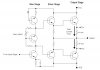
A input differential pair is shown here. The left transistor is the one receiving the input (think of as the 'inverting' input, as any signal applied to the base is inverted at the collector), and the right receives the signal from the output (the 'non-inverting' input). If an equal signal is applied to the base of both transistors, the output will be zero, as a diff amp only amplifies the difference between the two signals. If, say, a clean, non-distorted signal is applied to the input, but later amp stages distort the signal, the distorted signal is fed into the second transistor. Since the distorted signal is different than the original signal, the first transistor also amplifies it, but with an opposite polarity. When the signals are summed, the distortion is oddly missing. ;) So the signal being sent to the next stage is free of the distortion.

DC offset works much the same way. If DC is detected by the transistor connected to the output stage, its base current tries to change. Because of the current source, any change in current for the second transistor means an opposite change in current for the first, thus lowering the DC which is presented to the next stage, and lowering the DC which is eventually measured at the output.

inputstage_zpsl8cgxspv.jpg


So maybe this helps to show why measuring the DC offset at the output of an amplifier is a good, quick way to 'check the pulse' of the amp in general. Unbalanced input pairs are easily the #1 cause of poor amp performance and unexpected high levels of distortion (providing nothing else is obviously wrong, broken, or fried). Non-matched transistors, or transistors with damaged BE junctions, or very old transistors that have just drifted apart over the last 25 years (very sad...we used to be so close :cry: ) just need to be replaced with new ones...and modern transistors kick-butt on the old devices in most catagories, so it's a win-win situation.

Some good reading here, and here.
 
Last edited:
Thanks EW, I'll have to read into this more when I get a chance....

..... so your saying that the readings I got is nothing to worry about? although the right is 10mV higher then the left? Also my Receiver is 25years old (this month too, it was made in March, '78)

I mean what kind of improvments would I be looking at if I got both channels <4mV? anything much?

Thanks Again
 
Well, i have this sansui au-517 sitting in my closet because it has distortion and its protection kicks in after like 5 mins. so i tested the dc and in one channel it was 80 something mv and the other was like 230mv Is this why i can hear distortion from the amp and why after a few mins the protection kics in?. what do you think i should investigate first to try and fix the amp?? right now im in the process of restoring a Mcintosh MC240 tube amp and replacing all kinds of stuff but i have someone helping me with the technical stuff. although i know my way around inside electronics and stuff.
 
Uh Oh. My G9700 must be sick. If I did this correctly, I had a reading of -7.0 (200m scale) on the right but 480.0 (had to go to 2000m scale to get a reading) on the left. This was an Ebay deal that was received with distortion on the left channel. The tech y replaced an output transistor and some resistors and everything "sounded" pretty good. By the way, the output led's always show the right channel output one or two positions stronger than the left.

Now I am confused.
 
NW, with readings that low, it is a case of diminishings returns. For all the hassle of getting it lower, the audible gains will be quite minimal, if any. I am only trying to get it lower on the KA-5500 because I am using the amplifier section to drive my Heil AMT's, which, since being bi-amped, have no crossover capacitor between the amp and the tweeter to block DC, so offset here needs to be <10mV.

Haoleb, it is as good a place to look as any. An unbalanced pair could generate distortion as well as trip the DC protection (but so could a dozen or two other things..) When troubleshooting, let the failure occur (protection circuit) and start measuring voltages. Start with the DC offset, measured before the relay, of course. :) Suspect the driver transistors, input pair, and the VI limiter (your buddy should know where to look if he's technically inclined).

Wideone, the channel with 7mV is fine (+ or - doesn't matter). The other channel is indeed not well. Nearly half a volt and you should be hearing bad things from that channel. Sorry to say, but there are a lot of inbred assholes out there working on stereo gear. If the amp is worth keeping, it's worth fixing.
 
Last edited:
If your getting a - value, don't you just have the positive and negitive leads form the meter backwords?

EW, Thanks again, I'll just leave it for now, as it is running great, plus neither of the values are too high. Thanks
 
Originally posted by Night Wolf
If your getting a - value, don't you just have the positive and negitive leads form the meter backwords?
No. See the nifty schematic I posted a couple of posts up?? The only way to have 0V offset with a circuit like this is if the current gain of the transistors are exactly the same. Since we live in the real world, that is never going to happen. It matters not what the sign is, only that it isn't zero. The sign is just an indication of which transistor has the larger base current.

These amps run off of split supplies, like +/- 50V and more (often a lot more). A negative voltage is just as valid as a positive one. Why would measuring a negative voltage raise an eyebrow when measuring a positive one would not? Think about that...

As far as reversing meter leads, the negative speaker terminal is nearly always at ground (or at 'common') potential anyway. Always be a good little Techie :cool: and measure your voltages with reference to ground or common, and refer to them that way. Neg is Neg and Pos is Pos...don't flip meter leads just so the reading fits your sense of sensibility.
 
"just drifted apart over the last 25 years (very sad...we used to be so close "


LOLOLOLOL...............

Very informative post that seems to have made a lot of people run for their DVMs..... I only caution that performing internal adjustments like bias and balance can get one in trouble if not experianced and careful. One slip of a meter lead could short out an output transistor or a flacky bias pot can also send a output transistor 'west'. Best to have the service manual on hand which usually has procedures and pictures to assist in these adjustments. Access can be very tight and there are pretty high DC voltages on the larger amps and receivers.

I'm not trying to discourage anyone from learning and performing these kind of maintenace procedures, just be careful and ask lots of questions before jumping in. Measuring DC offset at the speaker terminals is pretty safe and should be the first thing you do before hooking up any speakers to that new find from a thrift store or e-bay purchase.

Lefty
 
Back
Top Bottom