grantly
Active Member
Hi all,
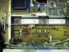
I went to an estate sale yesterday on a whim, and I was one of the first few people in the house. There was an incredible Barzilay cabinet with KLH 6s in custom cabinets. Way too much $$$ for me, so I decided to go to the basement. Right at the front was a cosmetically pristine sx-780 for low low $. I grabbed it, and took it home a little later (pics attached). Seriously, it looks like it just came out of the original packaging.
I probably should have fired it up on a DBT first, but I went ahead and plugged it in. I tested dc offset, and it was around 20mv on left channel, 13mv on the right. I adjusted DC offset according to the service manual, and I got it to about ~5mv on each channel. All good, right?
Well, I hooked it up, and while the right channel sounds excellent, the left channel is heavily distorted. It cuts in and out and bass especially breaks up. The meters seem to work fine (although left channel seemed to fluctuate a little with the extra distortion?). The distortion existed on multiple inputs - FM, aux, and phono with a TT hooked up. I probably should have tried it in mono, but I didn’t. I’ll also note that I haven’t touched anything with DeOxit either yet.
My first guess is the left STK Power pack. It doesn’t look like the internals of this have ever been touched - it’s super clean inside and out.
With all that said, I’m new to working on amps (other than using a good ol’ spray of DeOxit). I’ve built and rebuilt plenty of speaker crossovers, but 2 way and 3 way crossover schematics are relatively simple.
I thought maybe I should spring for the STK replacement modules that are available on the auction site (and buy the materials listed on the BOM in the details on the purchase page), but that repair would be a new level for me. I’m willing to do it, though. Frankly, I’m ready for the challenge.
Any feedback or direction would be appreciated. I plan on reading other sx-780 threads as well.
I’ll also note that this repair will take time - like a loooong time. I’ll update and post as I get to next steps. I’m a teacher and a coach, and my summer break is coming to a close very soon. I also have a one year old daughter, so a lot of the free time I once had is no longer free (but still good!).
My goal is to ideally get the problem diagnosed and repaired by the end of July 2020. You can quote me on that.
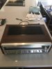

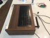

I went to an estate sale yesterday on a whim, and I was one of the first few people in the house. There was an incredible Barzilay cabinet with KLH 6s in custom cabinets. Way too much $$$ for me, so I decided to go to the basement. Right at the front was a cosmetically pristine sx-780 for low low $. I grabbed it, and took it home a little later (pics attached). Seriously, it looks like it just came out of the original packaging.
I probably should have fired it up on a DBT first, but I went ahead and plugged it in. I tested dc offset, and it was around 20mv on left channel, 13mv on the right. I adjusted DC offset according to the service manual, and I got it to about ~5mv on each channel. All good, right?
Well, I hooked it up, and while the right channel sounds excellent, the left channel is heavily distorted. It cuts in and out and bass especially breaks up. The meters seem to work fine (although left channel seemed to fluctuate a little with the extra distortion?). The distortion existed on multiple inputs - FM, aux, and phono with a TT hooked up. I probably should have tried it in mono, but I didn’t. I’ll also note that I haven’t touched anything with DeOxit either yet.
My first guess is the left STK Power pack. It doesn’t look like the internals of this have ever been touched - it’s super clean inside and out.
With all that said, I’m new to working on amps (other than using a good ol’ spray of DeOxit). I’ve built and rebuilt plenty of speaker crossovers, but 2 way and 3 way crossover schematics are relatively simple.
I thought maybe I should spring for the STK replacement modules that are available on the auction site (and buy the materials listed on the BOM in the details on the purchase page), but that repair would be a new level for me. I’m willing to do it, though. Frankly, I’m ready for the challenge.
Any feedback or direction would be appreciated. I plan on reading other sx-780 threads as well.
I’ll also note that this repair will take time - like a loooong time. I’ll update and post as I get to next steps. I’m a teacher and a coach, and my summer break is coming to a close very soon. I also have a one year old daughter, so a lot of the free time I once had is no longer free (but still good!).
My goal is to ideally get the problem diagnosed and repaired by the end of July 2020. You can quote me on that.
Last edited: