CATSCATSCATS
New Member
Hello all!
first post, and long time lurker.
I've had this little gem in storage for a couple years, and recently i have been upgrading my Hi-Fi setup, and i believe this receiver will be just the ticket.
Thrift store find: 20$
I have not tested the sound of the unit, to check the channels. I have only turned the power on, to check the lights, which seem to function properly (in hindsight i feel i should not have touched the power button, but at the time I did not know of the recall for the F1040 boards, and i still had not purchased the sansui, so if it was DOA then i would have left it at the store.), and I didn't let out any magic smoke, nor does the unit smell like or look like anything caught on fire.
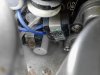
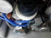
I popped the cover off the top and had a look inside: see attached pics.
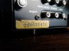
i think the S/N means it is from march 1970
I have some decent technical skills, and i can solder a bit. I don't have an issue with trying to repair the unit myself, but i have no test equipment (aside from a rudimentary multi-meter).
Id like to use the "skippy124 " mod to the bias transistors and bias diodes, but i am stuck,
The thread is old and photobucket is dumb and locked the pictures,
but mouser looks like they have all the components i need.
are the components a direct 1 for 1 swap?
can someone direct me on the manner in which they are installed? (including polarity of parts if necessary)
i can probably translate a schematic, but i am not electrically inclined, i'm more of a mechanical thinker.
Photos speak a 1000 words, i can replicate the fix visually, so photo would be ideal.
any help and advice i would really appreciate
thanks!
Scott
first post, and long time lurker.
I've had this little gem in storage for a couple years, and recently i have been upgrading my Hi-Fi setup, and i believe this receiver will be just the ticket.
Thrift store find: 20$
I have not tested the sound of the unit, to check the channels. I have only turned the power on, to check the lights, which seem to function properly (in hindsight i feel i should not have touched the power button, but at the time I did not know of the recall for the F1040 boards, and i still had not purchased the sansui, so if it was DOA then i would have left it at the store.), and I didn't let out any magic smoke, nor does the unit smell like or look like anything caught on fire.
I popped the cover off the top and had a look inside: see attached pics.
i think the S/N means it is from march 1970
I have some decent technical skills, and i can solder a bit. I don't have an issue with trying to repair the unit myself, but i have no test equipment (aside from a rudimentary multi-meter).
Id like to use the "skippy124 " mod to the bias transistors and bias diodes, but i am stuck,
The thread is old and photobucket is dumb and locked the pictures,
but mouser looks like they have all the components i need.
are the components a direct 1 for 1 swap?
can someone direct me on the manner in which they are installed? (including polarity of parts if necessary)
i can probably translate a schematic, but i am not electrically inclined, i'm more of a mechanical thinker.
Photos speak a 1000 words, i can replicate the fix visually, so photo would be ideal.
any help and advice i would really appreciate
thanks!
Scott