• The move to the new server is done. There are some software and database maintenance updates in process. This has us passing the hat around to help out. We appreciate any donations. Seriously, even a dollar helps. The payment page may be found here - https://www.audiokarma.org/support.html

Another 939 rebuild thread

The SWITCH is GOING as soon as i get the parts from Y'day's Audio. He could have put a switch box on the back with the lock switch on it to preserve the looks from the front. Or at least one that didn't beat the hell out of the subframe and the FRONT Panel. :bash:

I kinda like my gear as original as I can get it. If the parts aren't available I can see it, but that switch is just too much.:yuck::yuck:

Awww, that switch is the BOMB!
Maybe ALL the 70s gear should have had a key switch.

But then we'd all be asking around for spare keys.
:lmao:
 
Tell you guys what! I'll put the switch (with the KEY) up for AUCTION after I get the new switch and front plate.:scratch2:

May be I'll make enough $$$ to offset the cost of the new switch from Dan.:thmbsp: ...................NOT!!!

Get your very own "DOOMSDAY SWITCH".........Keep the Rugrats on their toes.:D
 
You could have the best of both, by returning the unit to stock, but put the power cord through a project box with the key switch mounted in the box to cut off power there! :naughty:
 
Yeah I could, but my kids are 30 and 27 and have no use for Dad's "Junk toys". Now as far as grandchildren, that's another story. Annabelle is 1-1/2 and has a KLH 20. She knows not to go near "Pop's sic sheen". She's learning! Now to get Billy a setup when he's older.(1-1/2 months).

Larry
 
Received the FACEPLATE (complete with all function switch covers, dial glass, and tuning knob back cover from Danny @ yesterday's Audio. He had it listed on the catalogue. There is a small hairline mark that is so light I had to put my camera in MACRO and get up within 6" to see it. You don't see it if you don't know it's there. Danny called it small, and boy is it ever. The glass has all the lettering in great shape, the plastic grommets are intact, the switch covers are great, and all the lettering on the faceplate is pristine. Great price too. Also got the HI/LOW/-20db switch panel, and oHm'ed it out . Get this. I ordered them Sunday EVENING and received them TUESDAY Afternoon. Less than 44 hours! WOW! The only way he could have gotten them to me faster would have been to drive from New York State to Maryland.

I tested the board with the oHm meter before I installed. Part Tested good. Swapped pins from one board to the other board. It's staying as is right now waiting on the parts from AK'er UNCLEBORT, who has graciously supplied the 3 ganged AUX power plug, the Front sub frame panel and the power switch, from a parts 1010 he has. This guy is what AK is about. I offered to pay for the parts, but he said parts are free. He declined shipping payment on the 3 gang. I'm insisting on at least paying for shipping on the subframe and switch.

For those that have 1010's and need some parts, he still does have a lot of parts for the 1010 yet. He probably doesn't have the faceplate tho. I know that the 3 gang Aux power plug, front subframe, and power switch are now gone. So check with him and ask him what he does have. He does have 3 kids, and they take up time (don't they all....and grandkids do too.) so if you need a part, be patient.

I'll take some more pics when i get the parts and do the install.

Thanks to Tom(Unclebort) and to Danny @ yesterday's audio.
 
Ordered the recap parts from Mouser this morning including a new relay and new trimmer VR's, but not the Filter caps. As it's now running fine, with no real issues other than the switches, I'm gonna hold off on the Filtercaps for a while. But it will have a close eye kept on it. I did this with my 1010 and it was almost 2 years before I broke down and replaced them. I know I'm treading on on thin ice.

I'll check the AC ripple voltage when I open it up, and again when it's finished. I replaced Low/Hi/-20dB switch and the faceplate y'day. With the power switch now gone (thank god!!) I'm not going to jumper the power leads even to test. I'll wait until I have the part installed.

Figure this should take a week to a week and a 1/2 based on one board a night except for the AMP which will take 2 nights. And it gets tested after each board.

We'll see how this one stacks up against a 1010. I know it's gonna be shy in the total WPC but it's been showing me some sonic qualities that the 1010 didn't have. Holographic sound if you will. But whether that will remain, remains to be seen.

Larry
 
After I straightened out the previous owners crap on the -20Db, and fixed the Mono switch, I plugged it in with meters on both sides at the speakers. NOTHING! Not a DAMNED Thing sound wise. Meters were reading between 5 and 10mv so the amp was idling ok. Meters and lights working as I ran it up and down the tuner scale. Just no sound. So I opened it back up and went thru everything I had worked on again with an oHm meter. Open circuit in the -20db switch. Open up the group(Low/HighFilter and -20dB) and found sliders only in the Low and High Filter switches. Looks like the guy lost the sliders and put in this 1/2 assed micro switch affair which had things going from stereo to mono but NOT dropping the level. Figured out I was getting a signal all the way up to the -20db switch. I closed it up for the night at that point. So for the interim until I can get a new switch panel (lots of traces lifted / gone on this board had to wire in the things), I'm gonna tie pins 1 and 2 together on the -20dB switch. At least I should get normal volume levels.

thanks for cap lists Mark. I'll check it against mine and make adjustments as needed. The 939 is Born on dated VJ (Oct. 75). Which puts it in the middle of my 434 (UL- Dec-74) and the 737 (WF-Jun-76).

I replaced the D313's and B507 on the Power supply along with the Diodes. And installed the Flyback Diode between 9 & 10 Cathode to 10. I'm gonna concentrate on the problem child transistors as I have plenty of replacements for them.

I'll cross check your list with what's on my unit. Make changes as needed. Will advise. This is gonna be a couple month project.

Larry

Hi kind of new to the Pioneer Forum and am following this with interest. I will be taking on a SA 9100. I have seen on alot of threads the mention of a diode across the #9 and #10 on the power supply board, what is the purpose of this and does it apply to all Pioneer power supplies as I am just finishing up a SA 7100 and want to know if that model is recommended to have this done. (and do you use a UF4004 diode?)
Also what are the other diodes on the SX-939 power supply you replaced, SIB-01-02's?

Thanks!
 
Can't wait to hear how this one compares Larry. I know I'm liking my "3" series now that it's back among the living!

Pat, my understanding of the flyback diode (that someone much wiser than I told me) is that it prevents voltage from flowing back to Q7 collector. Pioneer added it to later revisions and models as a matter of course.
 
Can't wait to hear how this one compares Larry. I know I'm liking my "3" series now that it's back among the living!

Pat, my understanding of the flyback diode (that someone much wiser than I told me) is that it prevents voltage from flowing back to Q7 collector. Pioneer added it to later revisions and models as a matter of course.

Thanks Bill, I will start a new thread for info, do not want to hijack.
 
Go Larry go, really keyed in to this rebuild :D
Taking your time is the key issue
And of course keep us keyed in to your progress
Btw since you started this thread are you the keynote speaker?
(could not resist)
-Lee
 
Let me clear up one item. FLYBACK DIODE is for the PROTECTION BOARD!! not the Power supply. Bill S hit it on the head as to the purpose and subsequent factory addition. 1n4007.

Patfont; I replaced the SIB01's with 1n4007's. I suggest you get the Service manual, and make a list of the caps. Then read the PIONEER TUNING FORK series on cap descriptions (cea, cssa, ceanl, etc) and adjust your list accordingly. PIONEER TUNING FORK GUIDE THREAD Suggest downloading all of them as they all contain good info on PIONEER GEAR, and can be used on other brands.

Here's a blurb from an old Mark the Fixer post on what and why....
Mark The Fixer's Cap rules of thumb (nichicon)

I use upw, uhe for general caps including signal coupling in that order depending upon stock "cea"
I use ues, uep & uvp in that order for bipolar depending on stock
I use ukl for low leakage caps (in sensitive areas they reduce the noise floor)"ceanl", "cssa", "csza"
0.1uf to 2 uf I use stacked film where they fit: DFS and ECQ

solid aluminum and tantalum caps get stacked film when possible, or ukl's otherwise. "cssa" "csza"

c?B means it's an axial cap = one lead on each end
c?a = radial = both leads on one end

Bill; It sounds good as is, but out of habit, I give them a 100,000 mile overhaul. Like an old car. Pull the engine and do a ring job, valve job, new bearings, gaskets, etc. Overhaul the brakes, etc....

Lee. :D :D

The power switch and front subframe get mailed tonight (mon). After I finish a micromatic turntable(doing run in now) and a 800C(about 1/2 done) I'll dig into the 939.
 
Last edited:
Let me clear up one item. FLYBACK DIODE is for the PROTECTION BOARD!! not the Power supply. Bill S hit it on the head as to the purpose and subsequent factory addition. 1n4007.

Patfont; I replaced the SIB01's with 1n4007's. I suggest you get the Service manual, and make a list of the caps. Then read the PIONEER TUNING FORK series on cap descriptions (cea, cssa, ceanl, etc) and adjust your list accordingly. PIONEER TUNING FORK GUIDE THREAD Suggest downloading all of them as they all contain good info on PIONEER GEAR, and can be used on other brands.

Here's a blurb from an old Mark the Fixer post on what and why....

Bill; It sounds good as is, but out of habit, I give them a 100,000 mile overhaul. Like an old car. Pull the engine and do a ring job, valve job, new bearings, gaskets, etc. Overhaul the brakes, etc....

Lee. :D :D

The power switch and front subframe get mailed tonight (mon). After I finish a micromatic turntable(doing run in now) and a 800C(about 1/2 done) I'll dig into the 939.

Hi Larry thanks for the clarification/education:

I took this in direct context:

I replaced the D313's and B507 on the "Power supply" along with the Diodes. And installed the Flyback Diode between 9 & 10 Cathode to 10. I'm gonna concentrate on the problem child transistors as I have plenty of replacements for them.

I get it now after looking at the schematics:

Coming from relay to Prot. Board on the ones I was looking at (SA-9100, SX-939) it comes in at pin 9 and 10, with cathode side to 10. Looking at the schematic for the SA 7100 I am working on it is pin #14 and 15 cathode towards pin 15.

I get it now thank you for your help as I am trying to learn the ins and outs and common updates/upgrades problems with Pioneer units. I am coming from Marantz forum and there is alot to learn here.

Sorry for the minor hijack here
 
Last edited:
PHASE 1 COMPLETE!

Received the Front subframe, Aux power plugs, and the power switch from AK'er UNCLEBORT who has a parts 1010. (Yes Virginia, Santa Claus listens to Early 70's PIONEER gear!) Thanks Tom. They fit perfectly and better yet everything WORKS!

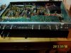
So on to some pictures. The top is off as I was doing some sanding on it prior to staining it.

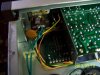
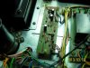
Showing the Aux Plugs, and new wiring run to the new power switch.
attachment.php

100_3992.jpg
Subframe and switch install complete.
attachment.php

100_3993.jpg
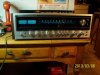
MUCH BETTER LOOKING!No Frankenstein switch. Right side up and turned on for testing. Relay clicks in 6 seconds. Just a bit slow.
attachment.php

100_3996.jpg
She picks up stations really well. There is absolutely NO ANTENNA on it and it's picking up a Baltimore Station that the Transmitter is on the Northwest side of town (about 40 miles from me.) In Stereo yet.
Mouser order enroute due on Friday. Then the fun begins for the weekend.

Larry
 
Last edited:
1 AW **** wipes out a years worth of ATTA BOYS!!!!

Well there go all the "ATTA BOYS" right out the friggin window. This is ONE BIG Mississippi sized AW SH#%!!!!!!

Spent 4 hours last night recapping the Equalizer board, muting board, Tone control board, Protection board, and installed a new relay. This morning I started on the Power Supply, Tuner and finished up this afternoon with the Main Amp board. Brought it up on the DBT with the Variac. NO SOUND! :wtf: Light's light, the meters work in FM and AM, Stereo light lights up, NO RELAY! Check the voltages from the Power supply to the protection board. Everything is as it is on the schematic. NO RELAY.

I pulled the jumpers and plugged in a patch cord from the pre outs to my 800C. I've got FM, AM, AUX, Phono, Tape Loops Just no amp.

I've got good rail voltages and I checked the bias and center voltages when I first powered it up (put in new 10K pots, forgot the other 2 were 100oHm D'OH!)
Checked and adjusted Center Voltage both sides 0.01vdc (R) and 0.02 (L) Bias is DEAD ON @ 50mv. NO DRIFT OVER 1/2 HOUR. Just NO RELAY.

RAIL Voltages are 48 and -48V. I checked for broken wires visually and with the meter between points from the Power supply and the protection board, and the Power supply to the Amp, and from the Protection board to the amp. Nothing broke. I even put the old relay back in. NADA! I get 36V on both sides of the Relay solenoid. That doesn't sound right. I've still got all the old transistors, so if I have to......... But I shouldn't as I checked all the transistors on my meter both in Diode mode and the hFe selector.

(Uncle Fester MOMENT!)
While I was typing this something in the back of my head (it's small so it wasn't a big something)told me to check the transistors in the protection board. So I grabbed the data sheets again and went thru the board. Nothing stood out. So I opened up the PIONEER Tuning fork on Troubleshooting Protection circuits.:headscrat It led me to check AGAIN Q7. So I pulled Q7 and it was fine. Then I pulled Q6 and put it in my meter to check hfe. I put it in as a EBC which is what the KSA733 is. I got a battery indicator (which is good for telling me I fuc#$d up again.). Wait a minute?!?!!!!:scratch2: PNP? Check! :thmbsp:EBC Check! :thmbsp:THEN I see the LAWYERS small print on the DATA SHEET:cry:SUFFIX "C" means CENTER COLLECTOR, Dumb A**" (ECB).

Oh **** it couldn't be that simple. So I checked the bag, and sure enough.....KSA733CGBU!!!!!!!!:withstpd:
The "COLLECTOR IS IN THE MIDDLE", STUPID!!Sooooooooooooo! I grabbed another one even tho this one still showed good, and fired it up. 5 seconds on the NOSE! CLICK!!!!! :yes:WE GOT MUSIC!!!!!!!


It's my fault for assuming (ass u me) that the transistor was as shown on the picture on the Datasheet. ANOTHER LESSON LEARNED. Mark the Fixer is probably gonna read this at some time in the future so I'll save him the aggravation of trying to slap some sense into me thru the internet.:twak::twak:


She's done except for the case which is still being sanded down enough that the chunks that stripped off with the vinyl are mostly smoothed out. Can't find my palm DA sander, so I'm doing it by hand.:tears: I'll probably just end up reveneering it.

Give me a week or so and I should be done with the case. But the 939 is done. Every last tantalum is History(Only 1 onthe whole thing).

It DO sound GOOD! Thanks to Ed for the 939. He had more faith in my abilities than I do at times. And thanks to UNCLEBORT for the parts. For any of you guys with SX-1010's he's got one for parts and all you have to do is ask. If he's got the part, you can have it. I'd suggest paying shipping at least. I've got the power switch, front sub frame panel, and the aux outlets.

Put a fork in me. I'm DONE! Pictures tomorrow....

Larry

 
Last edited:
Larry, I feel better now. I did the same thing a short while back on my 838. I know the feeling (head hung low and all). At least you figured it out quickly.

Glad it's all together. They put some nice tuners in those 3 series for sure. Mine picks up station signals my other receivers struggle with. Nice job!
 
Thanks Bill. The funny thing is I did the same thing on my old SX-1010 with a couple of transistors on the amp. Mark the Fixer was having Chest pains when I was working on that one. It was my first PIONEER and it took me about 2 weeks. And he beat it in my head (although not enough) to double check the Data sheets.

Ended up having to modify the order as one of the caps in the Power supply was on backorder. The caps I ordered were too LONG! So I'll order the originals when they come in and I do my next order. Already made up a wish list on Mouser.

Now for some more pics. Note that the RELAY cover is the old one. The NEW GUTS are in it. It's a super-tight fit but it does work. Thanks to Mark and Echowars for figuring this one out. No Modifications needed.

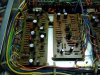
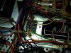
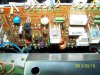
Equalizer and Protection boards
attachment.php

100_4016.jpg
Power supply.
attachment.php

100_4017.jpg
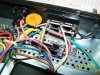
New power switch. needed wires from the Power plugs, so Routed new wires from back end.
attachment.php

100_4018.jpg
New Aux power plug, Main 6A fuse and new wiring to power switch. The fuse is the one that is normally encased in plastic sleeve and soldered in.
attachment.php

100_4019.jpg
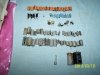
About 3/4 of the parts total replaced in 2 installments.
attachment.php

100_4021.jpg
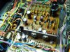
Tuner board. What a Pain to get out and put back in. But it works and better than before. No Alignment needed. It's actually got a dental pick clamped to it for an antenna now and picking up a station in Stereo where I know the Tower is 35 miles from me. Strength is 1 to 1.5. Nice and clear, no hiss, no interference.
100_4022.jpg
attachment.php
 
Last edited:
More pics.


Tone Control Board
100_4009.jpg
attachment.php


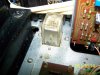
New Relay, Old Case.
attachment.php

100_4010.jpg
Muting board
attachment.php

100_4023.jpg
Left AMP. Note in the bottom left the lytic and the film. Schematic and board drawing have them reversed. I left orientation as is on board. For the techs it's C-1(0.47uf) and C-3 (1uf).
attachment.php

100_4025.jpg
Right AMP. Same note as Left Amp but C-2 and C-4.
attachment.php

100_4026.jpg
the only "MOD" I did. 3m Clear Self adhesive sheet. The blue is dark due to the black background of the transformer.
100_4024.jpg

attachment.php
 
Last edited:
And the LAST of the PICS. I rechecked the Center Voltage (L)0.01 and (R)0.02 then set the Bias to 50mv on both sides. After 1/2 hour no drift at all. I'll continue to check @ 1/2 hour intervals for the 1st 4 hours of a 48 hour burn in. So far so good.

New Relay old case. It was a tight fit getting it in the case.
attachment.php

100_4027.jpg
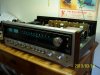
1st run up this morning. No problems.
attachment.php

100_4029.jpg
Different angle. Note the Stereo light and the Antenna. Dental pick screwed down on 300oHm connection. Tower to this particular station is 35 miles from house. Strength is just over 1. With regular antenna it's just over 3. I do have one bad light bulb behind the dial.
attachment.php

100_4030.jpg
Other than the 2 caps in the powersupply, the lamp and finishing the cabinet, it's done. This one is running great. Sounds a bit better than my 737.

If you are wanting a SX-1010 and can't get one, this is the closest you'll get to one. Looks to me the only real difference is 70WPC vs 100WPC. And the 70WPC is conservative. More like 80-85wpc if it's recapped and tuned up. Same basic layout. Switches and controls on front are almost identical. Internally there are some differences but they are minor. This is one of those overlooked units that has a lot of potential.

Larry
 
Last edited:
Back
Top Bottom