• The move to the new server is done. There are some software and database maintenance updates in process. This has us passing the hat around to help out. We appreciate any donations. Seriously, even a dollar helps. The payment page may be found here - https://www.audiokarma.org/support.html

Another Advent 300 Rebuild: My First

OK so I'm sure there are a lot of Advent rebuilds on this site but I figured its easier to start a fresh thread. I am new at this repair scene and was hoping folks could help me on my way as I make silly mistakes. I did review a handful of existing threads ahead of time so I had a starting point.

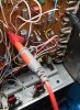
I picked up an Advent 300 marked as parts or repair. It does power on, however upon opening it up I immediately noticed two issues.
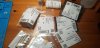
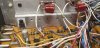
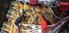
20210708_121933.jpg 20210708_121947.jpg
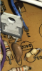
1. The lead for the original Mallory Power Filter caps was broken off at the base of the cap.
2. F401 the 3a fuse was blown.

Checked the Transformer and the Filter Caps after replacing the two old Malory caps with something newer.(Will replace with new final caps once I get everything ordered)
  • Transformer putting out 38.8 Vac
  • Filter Caps: 51.1 Vdc
Like a newbie, which I am... I replaced the fuse to try to see if I could test a few things. Nope... Blew that fuse then smoked cap c313(Replaced with a temp of same capacitance/higher voltage.)

Pulled all the transistors to test for shorts.
Q316 - 2N6490G: BAD
Q317 - F2N6490: GOOD
Q315 - 2N6487: GOOD
Q314 - 2N6487G: BAD
Q311 - C1345: GOOD
Q312 - C1345: GOOD

With the F401 fuse and the transistors out I tested the 15v Regulator at RA400
  • 25.5Vdc in / 14.43Vdc out (This seem ok, should I replace with something new?)
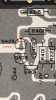
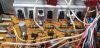
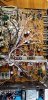
I then tested the test points on the board(not sure if this is the right way to test - See image below for example)
(AG = aux ground)
  • +22/AG: 25.5 Vdc
  • -22/AG: -26.5 Vdc
  • +15/AG: 14.43 Vdc
  • -15/AG: 1.27 Vdc <-- This seems wrong...
20210714_132226_Cropped.jpg

Parts I have in my cart for purchase at the moment - Suggestions are welcome!
2 - Mouser #:652-3329S-1-203LF
Bourns Trimmer Resistors - Through Hole 1/4"RND 20K 10% 0.5W ATTS

2 - Mouser #:647-LKS1V682MESZ
Nichicon 35volts 6800uF 20%

2 - Mouser #:863-2N6490G
Bipolar Transistors - BJT 15A 60V 75W PNP

2 - Mouser #:863-2N6487G
Bipolar Transistors - BJT 15A 60V Bipolar Power NPN

16 - Mouser #:532-56-77-11
Aavid Thermal Interface Products Thermalsil III Thermal Pad for TO-220, Mica Insulator, Rectangular, Opaque, 18.92x13.84x 0.051mm (Got a few extras just in case)

6 - Mouser #:594-D103M29Z5UH6UJ5R
Ceramic Disc Capacitors .01uF 100 V Z5U +/- 20% (Some of mine look cracked or missing pieces near leads)

1 - Mouser #:810-CC45SL3AD181JYGN
Ceramic Disc Capacitors D: 8mm 1kV 180pF SL 5% LS:5mm (This one looks weird/bad - c402 I think, its right next to C313 that smoked)

As for EL Cap replacements I was thinking I would do a complete replacement across the board using Elna RFS-SILMIC II (I also plan to replace the C104, C105 Cap. 4.7uF, Tantalum with Elna EL)

I was also thinking I might reach out to davidreaton.com to get the -15V regulator mod that I've seen several of you post about. Hoping that will fix the -15v issue posted above.

Open to any and all suggestions, Thanks!
 
Last edited:
Register to hide this ad
Ordered the parts above and the Elna Caps. I also ordered a replacement 15v regulator and its twin the -15v regulator for $0.50 each. Going to take a swag at it myself first. I'm hoping to get the 15v to 15v at least, I'm a little nervous about the negative one as all I have to go off of is chat and a picture from an earlier thread. ;)

I'll probably pull q401,402,403 to see if I can tell if bad. I wasn't having much luck finding replacements which I why I'll try the -15 regulator and if I can't figure it out I'll buy the kit and instructions from David's site. If those are not the issue I'll probably need to dig deeper on that side of the schematic.
 
Last edited:
If you want to replace the -15V MPSU52 supply circuit with a regulator I think you will need to pull out Q401 (replace it with a -15V regulator), remove Q402 and Q403 and add a jumper across Q403. I did this a while back end it made a difference with mine. I will post a photo later that shows this change.
 
If you want to replace the -15V MPSU52 supply circuit with a regulator I think you will need to pull out Q401 (replace it with a -15V regulator), remove Q402 and Q403 and add a jumper across Q403. I did this a while back end it made a difference with mine. I will post a photo later that shows this change.

That would be awesome!! I was able to see that the regulator went in 401, but I couldn't determine if and where jumpers were needed. That would be a huge help! Thanks

Watching. I am on the hunt for one of these myself for use as a preamp
Yeah, I might use the amp for a bit in my office but was initially intrigued with trying it as a preamp to a power amp.
 
Here are a couple of pics to show how I implemented the -15V 7915 regulator. I used a 0 ohm resistor for the jumper. Hope this helps.
 

Attachments

  • Advent 300 -15V -1.jpeg
    Advent 300 -15V -1.jpeg
    142.7 KB · Views: 95
  • Advent 300 -15V -2.png
    Advent 300 -15V -2.png
    696.3 KB · Views: 222
  • Advent 300 -15V -3.png
    Advent 300 -15V -3.png
    843.1 KB · Views: 92
Thanks Glensound, this is super helpful and looking at the parts layout makes more sense now.
:beerchug:

I should get most of the parts on Monday so I should have updates mid next week!
 
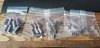
Mouser order has arrived!!
20210720_160914.jpg

I've replaced the positive regulator along with new insulator and grease. We are now a solid 15Vdc on the output and test points. Also replaced the trimmer resistors with Bourns.
Question: I've seen people suggest replacing the large brown resistors in front of the trimmers. Is there a reason for this? I did buy replacements for the 4 on the board but I wasn't sure if there was a reason, they look ok.
20210720_162048.jpg


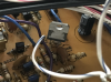
Next I performed the above referenced -15 regulator modification however I am not seeing the proper numbers on the input/output or test points. Ended up using a solid core 24AWG wire for the jumper.
I know the input being too low is causing the output to be incorrect. I'm thinking maybe I need to get the remaining transistors and 3 amp fuse reinstalled to test this perhaps. Does anyone know for sure?
Or and suggestions on where else I should be looking?
20210719_230950.jpg20210719_215444.jpg

I plan to try to get the output transistors installed this evening or next as time permits. Still waiting on all my EL caps to show up. Any day now... (I hate not getting tracking info! :rflmao:)
 
Photo from post 7 above @Glensound. Looks like you didn't twist leads around. Replacement is not a transistor, hence the leads are not in the same positions..
index.php
 
Main Transistors installed. doubled checked they were all in proper working order before placing.
20210720_221841.jpg

For reference fuse F401 needs to be in to get a reading of the -15 test point. YES, -15Vdc!!! -15.17 but still. Woohoo :banana:, and the fuse didn't blow this time!
20210720_224241.jpg
 
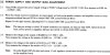
If anyone was interested when the service manual says to adjust bias pot to obtain 0.003 VDC across R330 and R332. Then R331 and R333. I believe this is what they mean...
I'll have to recheck this once I recap the board but I wanted to see if I could get close to the right numbers as is. So far so good...
20210720_230906.jpgadjust.jpg
 
I remember the filter cap lead on mine broke--around 1981. Yours lasted a long time.

Hahahaha, I guess so...
I got mine broken so who knows but yeah for all original caps it did hold up against time pretty good.
There is some case rust I need to deal with and had some broken transistors but all in all it held up.
 
Photo from post 7 above @Glensound. Looks like you didn't twist leads around. Replacement is not a transistor, hence the leads are not in the same positions..
index.php
I have setup as follows with heat shrink on the bent legs so they don't accidentally touch.

neg15Reg.png

Looking at the tracing/parts layout it makes perfect sense why my -15v was not showing the right voltage with the fuse out. hahaha, follow the fuse to the in of the regulator out to the -15 test post. lol :crazy:
 
Last edited:
Mini Update - Caps have arrived... Mass replacement to commence.
20210722_123803.jpg

Using the replacement size suggestions from David's Parts list. Plus, I'm replacing the 4.7uF, Tantalum with Silmic II 4.7/25v
Caps on power supply rails have been increased in capacitance and/or voltage
 
It's too late, and I'm not suggesting that the OP reconsider, but I would like to add my usual comment about the -15V regulator, for future restorers to ponder: I don't think it is an improvement to replace it with a fixed regulator.

The original design is a "mirror" regulator; that is, any variations in the +15V supply are mirrored on the -15V supply, which helps keep the variations out of the audio signal. If the Advent designers didn't think this was important, why wouldn't they have chosen a fixed regulator to begin with? I believe -15V 3-pin regulators were readily available at the time, and would probably have lowered parts cost compared to the mirrored design.

I can imagine that contemporary fixed regulators might perform so much better (compared to the ones available to Advent at the time) that the point may be moot. But not knowing that for sure, I figure I'll stick with the original design in my 300 projects. If nothing else, I admire its elegance.

Cheers,

chazix
 
It's too late, and I'm not suggesting that the OP reconsider, but I would like to add my usual comment about the -15V regulator, for future restorers to ponder:
Cheers,
chazix

It's an improvement to broken. Hahahah
Yeah, I could see that being possible. I wondered why but that could totally make sense. Thank you for sharing. I do still have the original parts. I'll test this out and if anything seems wonky maybe I'll try to put them back. Who knows...

Mine may not have actually been bad, I thought it was because the voltage was way off. Turns out you need that fuse in place. Hahaha

I'm learning based off what I hear from others. Hoping my mistakes and successes can help others in the future.

-Freq
 
Last edited:
All EL Caps have been replaced on my boards. Bias set to 0.003vdc, and all voltages within good range. Need to finish up by cleaning my case(little rust) and cleaning or replacing the RCA jack inputs(mine are filthy).
Note: If using the Capacitor List counts on David's 300-parts-list. Count the 1uf and 10uf caps on your boards, I ended up with two extra 1uf and was short two 10uf. Not a big deal as I had extra 10uf caps in my parts bins.

Anyone want to help me figure out my oscilloscope next? :idea:
I'll post some info later today or tomorrow.


20210725_012402.jpg
 
Back
Top Bottom