

You are using an out of date browser. It may not display this or other websites correctly.
You should upgrade or use an alternative browser.
You should upgrade or use an alternative browser.
Another AU717 restoration
- Thread starter skippy124
- Start date
Well done Skippy124 ! Its nice to see another Sansui being Refurbished to 'As
new " Technically and cosmetically.....what a wonderfull job you guys have done ! Congratulation ! Having been manufactured in the 70's and now over 30 years later, it sees the light of day ! BTW, what Caps are you people using ? Our Technician over here in Malaysia mostly use Elna Silmic II and Panasonic for the Power Board. AU-717 sells very well in ebay and Resale
value is always there.
new " Technically and cosmetically.....what a wonderfull job you guys have done ! Congratulation ! Having been manufactured in the 70's and now over 30 years later, it sees the light of day ! BTW, what Caps are you people using ? Our Technician over here in Malaysia mostly use Elna Silmic II and Panasonic for the Power Board. AU-717 sells very well in ebay and Resale
value is always there.
Thanks to all those who have posted above, your comments are very much appreciated :thmbsp:
My "weapon of choice" for removing the glue is a strip of FR4 PCB material about 10mm (3/8") wide and about 200mm (8") long, with a chisel edge filed at one end. Allows the glue to be scraped off without marking the PCB.


Cheers
John
. May I ask how you remove the glue? what in particular do you use?
My "weapon of choice" for removing the glue is a strip of FR4 PCB material about 10mm (3/8") wide and about 200mm (8") long, with a chisel edge filed at one end. Allows the glue to be scraped off without marking the PCB.
Cheers
John
BTW, what Caps are you people using ? Our Technician over here in Malaysia mostly use Elna Silmic II and Panasonic for the Power Board.
I use a mixture of Nichicon HE and Panasonic FC (it depends on what is readily available from where I source most of my components from - RS Components or Element14). The HE's are used for the larger values (they tend to be a good physical fit too, and are cheaper and in most cases are better spec'd than the FC's). For the 1uf and 0.47uf values I use Panasonic stacked films.
Cheers
John

larry777
Active Member
WOW,what a great job you are doing on this amp. I have an AU-717 that I was thinking about replacing the caps on also, mainly due to age,as overall it works good. I bought it new in 1978 and its had no work done on it yet. I did take note of your comment that you will provide a Capacitor Parts List when you are finished....which would be a Big Help to me. Thats part of the reason I didn't start anything yet ( As I don't have a total Caps list with size and values etc yet ). I will be watching for an update very closly,and thanks for sharing.
Last edited:

I have an AU217 with a weak left channel... this thread should come in handy a bit... just not sure where to start. When cleaning the glue, did you use any cleaner or just the scraper? As well, is the brown bits on the bottom of a PCB that just cracks off like amber is that the glue, or remnants of flux from assembly? Thanks

pete_mac
Super Member
I have an AU217 with a weak left channel... this thread should come in handy a bit... just not sure where to start. When cleaning the glue, did you use any cleaner or just the scraper? As well, is the brown bits on the bottom of a PCB that just cracks off like amber is that the glue, or remnants of flux from assembly? Thanks
Fuse resistors are likely to be the culprit. Check out skippy124's informative thread on this topic.

WOW,what a great job you are doing on this amp. I have an AU-717 that I was thinking about replacing the caps on also, mainly due to age,as overall it works good. I bought it new in 1978 and its had no work done on it yet. I did take note of your comment that you will provide a Capacitor Parts List when you are finished....which would be a Big Help to me. Thats part of the reason I didn't start anything yet ( As I don't have a total Caps list with size and values etc yet ). I will be watching for an update very closly,and thanks for sharing.
Thanks,
I haven't done the equalizer or tone boards as yet, but I do have another 717 in for a full recap so I will put up a full list soon
Thanks John! A superb job, as usual. It is encouraging to follow your work - so much patience, attention to details, informative comments, and pride in your work.
You set the mark kinda high - - -
:thmbsp:
I have an AU217 with a weak left channel... this thread should come in handy a bit... just not sure where to start. When cleaning the glue, did you use any cleaner or just the scraper? As well, is the brown bits on the bottom of a PCB that just cracks off like amber is that the glue, or remnants of flux from assembly? Thanks
Nice! Many thanks... now I must ask... if mine is mark I and the thread shows the mark II, is it safe to say the same locations exist but to use values from the resistor bodies? I cannot find the mark I schematic.
Hi,
Just used the scraper, with some isopropyl alcohol and a cotton bud to finish off. The brown bits on the bottom of the PCA is flux residue. The fuse resistors in the 217 should be the same as in the 217II, and PM me if you want a copy of the 217 service manual
Cheers
John
Time for a little update!!
I have recently received a little something from Canada in the post
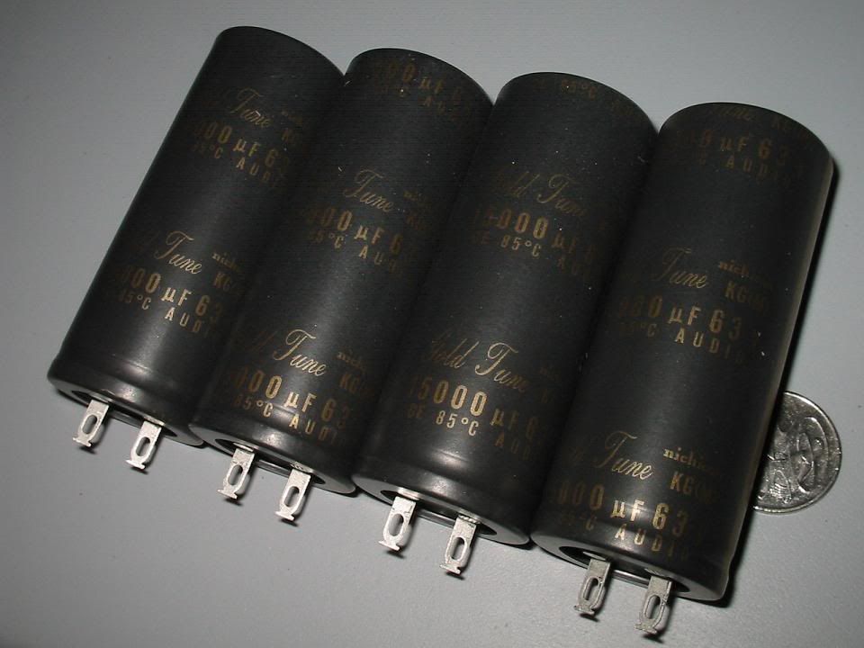
These will be fitted shortly, along with the 10 turn Bias pots.
And today, I received something that I had been waiting for for a while now, but it was worth the wait
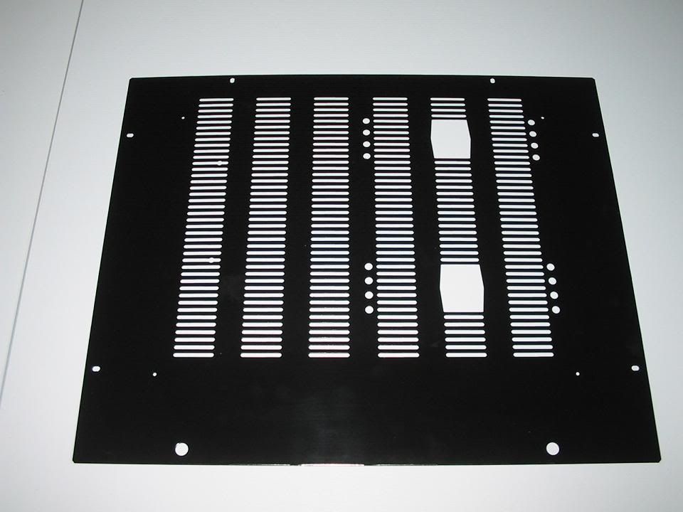
A brand new baseplate to replace the one that was missing when I acquired the amp. Very happy with the way it turned out!!!!
Looking forward to getting these last items fitted and then having some serious listening time.
Cheers
John
I have recently received a little something from Canada in the post
These will be fitted shortly, along with the 10 turn Bias pots.
And today, I received something that I had been waiting for for a while now, but it was worth the wait
A brand new baseplate to replace the one that was missing when I acquired the amp. Very happy with the way it turned out!!!!
Looking forward to getting these last items fitted and then having some serious listening time.
Cheers
John

Canada? Would you mind sharing where the main caps came from?
BTW, excellent resto!
Got the caps from Partsconnexion
Cheers
John

Uncle Bambi
Funky Tut
Very, very nice work!
I've got a question on the fuse resistors.......
I've rehabilitated a couple of Sansui's with the help of you and the forum,and I've always changed the fuse resistors as directed when someone was kind enough to identify them for me. My question is this - how can I identify on my own which resistors are the fuse resistors in any given Sansui unit? Maybe I'm missing something obvious, but they don't seemed to be marked as such in the SM, and they don't look any different to me.
So - how does one tell which ones they are?
I've got a question on the fuse resistors.......
I've rehabilitated a couple of Sansui's with the help of you and the forum,and I've always changed the fuse resistors as directed when someone was kind enough to identify them for me. My question is this - how can I identify on my own which resistors are the fuse resistors in any given Sansui unit? Maybe I'm missing something obvious, but they don't seemed to be marked as such in the SM, and they don't look any different to me.
So - how does one tell which ones they are?

Very, very nice work!
I've got a question on the fuse resistors.......
I've rehabilitated a couple of Sansui's with the help of you and the forum,and I've always changed the fuse resistors as directed when someone was kind enough to identify them for me. My question is this - how can I identify on my own which resistors are the fuse resistors in any given Sansui unit? Maybe I'm missing something obvious, but they don't seemed to be marked as such in the SM, and they don't look any different to me.
So - how does one tell which ones they are?
Often they are marked on the schematic, if the question is regarding an AU-517 or AU-717 & fuse resistors - they are definitely marked as such on the schematic.
Otherwise quite difficult to pick out, as they can be grey, blue and possibly other colours. The resistor bodies are often matte and rough looking, however there are a lot of grey resistors with a matte finish (smooth) that are not fuse resistors. Others may be able to pass on their experiences in this regard, but if you are having doubts about a particular resistor, just ask here !
So many of us have had nasty experiences with drifted or open fuse resistors, that the event is often burnt into our memories never to be forgotten.
Last edited:
Uncle Bambi
Funky Tut
Often they are marked on the schematic, if the question is regarding an AU-517 or AU-717 & fuse resistors - they are definitely marked as such on the schematic.
Otherwise quite difficult to pick out, as they can be grey, blue and possibly other colours. The resistor bodies are often matte and rough looking, however there are a lot of grey resistors with a matte finish (smooth) that are not fuse resistors. Others may be able to pass on their experiences in this regard, but if you are having doubts about a particular resistor, just ask here !
So many of us have had nasty experiences with drifted or open fuse resistors, that the event is often burnt into our memories never to be forgotten.
Well, in this case I'm interested in the AU-D7 I'm currently wrestling with. But in the interests of avoiding a thread-jack..... generically speaking (or in the case of the AU717), how are they designated in the schematic? Whats the symbol or nomenclature?
Hi John
There is some generic info here on fuse resistors
http://www.audiokarma.org/forums/showthread.php?t=430439
If post in that thread I'm sure you will get some specific answers.
Cheers
John
There is some generic info here on fuse resistors
http://www.audiokarma.org/forums/showthread.php?t=430439
If post in that thread I'm sure you will get some specific answers.
Cheers
John
Aha !
Hi John, I'd forgotten about that thread and the fact that you are the Fuse Resistor Maestro
To UB
Regarding the AU-517/717 and nomenclature which may or may not be the same on the AU-D7 schematic ' *3 ' is how they are indicated.
(Ooops more thread-jacking - sorry John)
To John - those caps are the only way to go with an AU-517 or AU-717 :yes:
Hi John, I'd forgotten about that thread and the fact that you are the Fuse Resistor Maestro
To UB
Regarding the AU-517/717 and nomenclature which may or may not be the same on the AU-D7 schematic ' *3 ' is how they are indicated.
(Ooops more thread-jacking - sorry John)
To John - those caps are the only way to go with an AU-517 or AU-717 :yes:
Uncle Bambi
Funky Tut
Thanks, guys!
Hi John (Hyperion), UB is also John, (a bit confusing hehe), I was directing my previous post to him.
no probs er the thread hijacking, it's all good info!!
Agreed, those caps are perfect replacements, looking forward to getting them installed
And if anyone needs a cad drawing of a 717/719 base plate let me know, I had three made (one for my 717, one for Pete's 719 - the 719 baseplate is unpainted, and one spare for future restorations).
Cheers
John
Edit: Hi UB, Ha a quick look at the AU-D7 schematic, it doesn't show any fuse resistors, but I will post up some of the schematic tonight in the fuse resistitor thread showing where I would look for fuse resistors.
no probs er the thread hijacking, it's all good info!!
Agreed, those caps are perfect replacements, looking forward to getting them installed
And if anyone needs a cad drawing of a 717/719 base plate let me know, I had three made (one for my 717, one for Pete's 719 - the 719 baseplate is unpainted, and one spare for future restorations).
Cheers
John
Edit: Hi UB, Ha a quick look at the AU-D7 schematic, it doesn't show any fuse resistors, but I will post up some of the schematic tonight in the fuse resistitor thread showing where I would look for fuse resistors.
Last edited: