• The move to the new server is done. There are some software and database maintenance updates in process. This has us passing the hat around to help out. We appreciate any donations. Seriously, even a dollar helps. The payment page may be found here - https://www.audiokarma.org/support.html

Another F-2624 bias problem

faccan

New Member
Hello, I'm working on a 7070 that the relay doesn`t "click".
I had changed both 1 omh fuse resistors in power supply board, all the fuse resistors of the F-2624 and deoxided the presets.
I tried to set bias current of one channel starting from maximun resistance in preset ( It have the F-2624 transistor version) and bias current started from 1.2 mA going up but when the bias current is 8mA or so it jump to 110mA !!! If I start to go down it descent form 110ma to 40ma where it jump to 2ma. If I start to go up again the cycle repeats. .
This channel doen´t work
The otre channel work without any problem and I can set 30 mA starting from 1.2 mA.

I'm meaning that I'am setting the bias current moving the preset.

I changed TR09 and TR10 because I thought that the problem could be there but nothing change.
The presets are working good because I meassure the resistance and they doesn`t jump and keep lineanity.
Output Transistors are good and I meassure all transistor in F-2624 and appears to be OK.
Any ideas where to look or target to?
 
Register to hide this ad
Do you have an oscilloscope? If so look at the output as you adjust the bias and see if it is oscillating. Do not connect it to speakers!
 
Hello, I'm working on a 7070 that the relay doesn`t "click".
I had changed both 1 omh fuse resistors in power supply board, all the fuse resistors of the F-2624 and deoxided the presets.
I tried to set bias current of one channel starting from maximun resistance in preset ( It have the F-2624 transistor version) and bias current started from 1.2 mA going up but when the bias current is 8mA or so it jump to 110mA !!! If I start to go down it descent form 110ma to 40ma where it jump to 2ma. If I start to go up again the cycle repeats. .
This channel doen´t work
The otre channel work without any problem and I can set 30 mA starting from 1.2 mA.

I'm meaning that I'am setting the bias current moving the preset.

I changed TR09 and TR10 because I thought that the problem could be there but nothing change.
The presets are working good because I meassure the resistance and they doesn`t jump and keep lineanity.
Output Transistors are good and I meassure all transistor in F-2624 and appears to be OK.
Any ideas where to look or target to?
As @Tom B suggests, the BIAS trimmer appears to be intermittent, and don't always show on a "test sweep" with a digital meter. I always replace the BIAS trimmers on these boards. You don't know how many cycles they have seen over the years, and trimmers have a limited cycle (turn count) life.
 
Likely culprits:
1. Bias pot.
2. Amp is oscillating.
3. Bad transistor that suddenly starts to pass current when the drive is turned up.
Replacing every component is NEVER a good method. That's called "shotgunning" and is not real troubleshooting. You never find out what the actual problem was and you don't really know if you fixed it, especially if the problem is intermittent.
 
You could check resistors on the bias network too... they are R27, 25, 23 on one side and R28,26,24 on the other, I remember one fellow that have some weird stuff on those causing havoc. (probably someones creative solution)

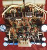
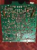
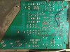
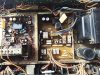
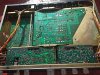
A good resolution picture of the board (both sides) would help too, at least with a visual inspection, since the some work has been done.
 
Likely culprits:
1. Bias pot.
2. Amp is oscillating.
3. Bad transistor that suddenly starts to pass current when the drive is turned up.
Replacing every component is NEVER a good method. That's called "shotgunning" and is not real troubleshooting. You never find out what the actual problem was and you don't really know if you fixed it, especially if the problem is intermittent.


I'm totally agree with what you said.
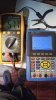
It' is oscillating at a very high frecuency. 1.4 Mhz
This is same setting when start to oscillate and then when turning off and on again without oscilating
WhatsApp Image 2021-07-26 at 7.48.27 PM.jpeg WhatsApp Image 2021-07-26 at 7.48.07 PM.jpeg

The other channel doesn't oscilate.

I think that perhaps any of the ceramic capacitor are not doing contact but it doen't seem to be the problem.
I found that C19 to C22 are poliester 8.2 nF but in the schematic they suppose to be 1 nF.

Any idea how to go on ?
view
 
Did you change any other transistors besides tr09/10 ? i doubt c19 and c21 would be the culprit. Sometimes when zobel network(it looks like on this amp it is on F2625) is not connected amp might oscillate. Also you may try injecting small capacitor(around 20 - 100pF. ) between collector of TR1 to base of TR3
 
Last edited:
I try with a 100pF
Did you change any other transistors besides tr09/10 ? i doubt c19 and c21 would be the culprit. Sometimes when zobel network(it looks like on this amp it is on F2625) is not connected amp might oscillate. Also you may try injecting small capacitor(around 20 - 100pF. ) between collector of TR1 to base of TR3

Thanks for the answer... I Try with a 100pF between collector of TR1 to base of TR3 and it went worst, I Burnt the 250mA of the multimeter. No others transistors changed
 
ok i hope that 100pF cap had appropriate voltage rating and personally i would use something like 30PF first. Anyway it did not work.. I assume the other channel is fine. Question did you check connection to F2625? also is there anyway to flip connections 13 (on board points 37,38) and 27 (on board points 49,50) F2625 just want to make sure it is not somehow connected to Zobel network. Anyway check very careful connections from board 2624 to 2625. Inspect on the board F2625 (not on F2624) C19 and R23 and connections around that area i would look at L01,R21
 
Last edited:
Maybe if you post a nice size, in focus, picture of the board we might be able to better assess what's going on here.

Thank for your suggestion!

Some comments of the Pics:
- 2624 TR1 and TR3 are 2sc1845 (and not the original 2sc1708 whichs are working also but I wanted to try) that is why they are in reverse position of the TR2 and TR4 ( BCE vs ECB pinout)
This is the channel that has the oscilation which still has the injected capacitor.
I changed the trimpot just in case...
I Measure every transistor of the oscilating channel and almost every component.
F_2624_component_50.jpg f_2624 solder_50.jpg F_2625_Component_50.jpg F_2625_solder_50.jpg 7070_Componet_33.jpg 7070_solder_33.jpg
 
Last edited:
ok i hope that 100pF cap had appropriate voltage rating and personally i would use something like 30PF first. Anyway it did not work.. I assume the other channel is fine. Question did you check connection to F2625? also is there anyway to flip connections 13 (on board points 37,38) and 27 (on board points 49,50) F2625 just want to make sure it is not somehow connected to Zobel network. Anyway check very careful connections from board 2624 to 2625. Inspect on the board F2625 (not on F2624) C19 and R23 and connections around that area i would look at L01,R21

I will connect the 2624 board Reversed to the 2625. I will check that are simetrical pinout first. We will see.
 
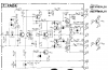
You're on the right track but wrong transistors! See the circuit below.
upload_2021-7-28_18-17-43.png
C13 and C11 are Miller caps. They increase the capacitance at the base of the transistor to insert another pole in the frequency response and either add some phase shift or make it roll off at a lower frequency so the gain drops below unity gain below the point where the amp is unstable.
The first thing to do is make sure the output transistors are original. Compare them with the other channel. If they appear to be identical, replace C11 and C13 with ceramic NPO/COG type caps of the same value and same or greater voltage. It worked at one time so it's probably a failed component.
 
You're on the right track but wrong transistors! See the circuit below.
View attachment 2299767
C13 and C11 are Miller caps. They increase the capacitance at the base of the transistor to insert another pole in the frequency response and either add some phase shift or make it roll off at a lower frequency so the gain drops below unity gain below the point where the amp is unstable.
The first thing to do is make sure the output transistors are original. Compare them with the other channel. If they appear to be identical, replace C11 and C13 with ceramic NPO/COG type caps of the same value and same or greater voltage. It worked at one time so it's probably a failed component.
+1 what dr*audio said.
I did ask if you changed any transistors because I did have a case when replacing input differential pair with another transistors ( ztx in my case) caused high frequency (around 1.4MHz) oscillation.Injecting capacitor between the output and inverted input solved the issue.
As Dr*audio mentioned C11 and C13 would "slow" down a bit Tr05 and Tr11 (see equivalent representation of transistor and it's corresponding frequency response which would also depend how it is connected).
NPO/GOG is a good thing however caution should be exercised and here is why. Regular ceramic capacitors which are installed in your unit are not NPO/GOG and it's capacitance known to decrease based on constant voltage applied to it.
So for example 100pF Ceramic cap might be in reality only 50pF or even less under the applied voltage ( higher the constant voltage applied lower the effective capacitance). I suspect that is why we often see in a service manual one value but in reality inside the unit another value is installed and notice it is usually higher and i guess it is because of the reasons above. NPO/GOG from the other hand DO NOT have dependency of it's capacitance from the applied constant value and i offten wonder if by replacing existing cap with NPO/GOG in 1 to 1 ratio in terms of value we are overcompensating.

I also wanted you to check Zobel network (resistor in series with the capacitor) Sometimes when those are not connected it causes high frequency oscillations. Your Zobel network is located on the same board with the protection relay (F2625). That is why i wanted you to flip those wires to see if anything changes.
 
Last edited:
Back
Top Bottom