• The move to the new server is done. There are some software and database maintenance updates in process. This has us passing the hat around to help out. We appreciate any donations. Seriously, even a dollar helps. The payment page may be found here - https://www.audiokarma.org/support.html

Another inop SX-1250 (Sorry)

zebulon1

Retired finally and having a blast on the bench
Subscriber
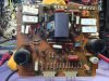
I bought this broken SX-1250 from a guy on Ebay and received it last week. He gave a brief description saying that he had it serviced recently and shortly after that it quit working. No sound and that the one heat-sink was very hot.

I checked the fuse’s and found all intact except the main 12 amp fuse (FU6) open. I checked the micro temp resister and that tested good (I checked it in circuit and shows 1.5 ohms lead res.). All but one of the four output transistors on the left heat-sink is shorted. I removed the driver board associated with the left driver heat-sink AWH-048A and did a visual check. No blown-out components, all the transistors check (ECB, no shorts) good in circuit. The wire ceramic wound resistors (.5k ohms) when lifted, read .8 ohms resistance. The large power supply filter caps look like they were leaking as evidence seen on the bottom cover (AdComs are on order). I ordered the recap list MTF posted on 8-20-2013 (Not the whole Darn thing, (Nice work! Thanks MTF) I used Matt’s to compare against, Thanks Matt). I did order the soft start relay as well.

This set looks like was used in a Honky-Tonk its whole life. It will clean up well after some much needed TLC. As learned here on AK repair then restore.

Any thoughts on what may have happened and what else I should look at? This afternoon I plan on going through the driver board with a fine tooth comb, lifting and checking each component. Thanks for any help.

attachment.php


attachment.php


attachment.php
 

Attachments

  • sx-1250 1.jpg
    sx-1250 1.jpg
    95.3 KB · Views: 496
  • sx-1250 2.jpg
    sx-1250 2.jpg
    80.5 KB · Views: 494
  • sx-1250 3.jpg
    sx-1250 3.jpg
    68 KB · Views: 495
Register to hide this ad
driver board on the blown transistor side. if the stv wires are ok, next is the pot opening up. check EVERY transistor and resistor on the driver card for that side.
 
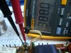
I lifted and checked all the transistors and resistors and they checked within specs. Lifted the diodes and checked, no faults found. Before I checked the pots for sweep I checked the resistance on each pin. VR1 reads as a 2k (The schematic has it listed as a 470 ohm?) pot. When I measure the center to each post I get 1.3K and .9k, relatively centered. VR2 was turned almost to the clockwise stop as seen in the picture below. A 470 ohm pot was adjusted to 390 ohms. I did remove both from the board, VR1 and VR2 and double checked my on board measurements. I did not check any caps.

The STV-3H diodes read one-way 1.456 dc on the fluke diode setting, open the other; Good.

I misread the ceramic resistors. They are .5 ohm (I thought they were .5K ohms) wire-wound and read .8 ohms when checked (lifted).

Would a misadjusted VR2 cause the output drivers to fail like they did?

So far I have three output drivers, the main 12 amp fuse open and VR2 pot on the driver board cranked to the stop.

The seller had the set at the shop and did not tell me the reason why (The repair shop and date, 10-10-13 are on a sticker on the back of the set). I wondered if he wanted to sell it in working order. The shop got it working, but only for a short time. He sold it to me in a non-working condition. Just speculation.

Thanks MTF for your help. :thmbsp:

attachment.php
 

Attachments

  • sx-1250 vr2.jpg
    sx-1250 vr2.jpg
    69.3 KB · Views: 473
That VR2 390 ohms seems to be quite high. It would have caused a very high idle current = heat...
 

Attachments

  • sx-1250 plastic standoff.jpg
    sx-1250 plastic standoff.jpg
    88.6 KB · Views: 123
I am rebuilding the stabilizer board completely and waiting for another, hopefully last Mouser order. I only made two on this set, I’m getting better! I am researching past posts getting ready for the first power-up on this 1250 and getting the function lights straitened out.

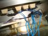
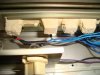
The light assemblies are a little toasted as you can see. I bought extra lamps from dwojo.com for my other SX sets, 1050, 950 and will be replacing all of them on this 1250. Kind of a nest!

attachment.php
 

Attachments

  • sx-1250 function lights 1.jpg
    sx-1250 function lights 1.jpg
    70.2 KB · Views: 427
  • sx-1250 function lights.jpg
    sx-1250 function lights.jpg
    69.6 KB · Views: 30
Those lamp holders seem like they would just explode as soon as you touch them. Unfortunately, short of manufacturing replacements, I don't know where they might be available. Hopefully one or more of our more experienced mentors has encountered this and found an easier solution. AFAIK, there is no good way to revitalize the natural rubber and vinyl once the oils in it have been dried out like that. A 3D printer might also be a possibility, since they can build up lots of interesting forms and features, but you would need at least one good part for modeling the item. Even then, LEDs would be necessary to keep the heat to a minimum.
 
The problem with the LEDS is that they generally emit on their axis, while this function lamp placement expects a SIDEWAYS emission.
 
The housing is as hard as a rock. I don’t think the proper replacement lamps were installed. The far left dial lamp is directly behind and very close to that light assembly. Is this toasted lamp housing a chronic problem with the 1250 sets?
 
Last edited:
The housing is as hard as a rock. I don’t think the proper replacement lamps were installed. The far left dial lamp is directly behind and very close to that light assembly. Is this toasted lamp housing a chronic problem with the 1250 sets?

Hey Zeb,
Maybe you could get a used faceplate with better rubbers inside?
Better rubbers is always good ya know. :yes:
 
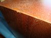
I took the decal off on the side of the wood cover and discovered this very nice original finish. I like it. It is a more natural Walnut color. I removed the decal because I am getting ready to replace the walnut veneer. This is the first time ever I saw this.

attachment.php
 

Attachments

  • sx-finish differance.jpg
    sx-finish differance.jpg
    79.5 KB · Views: 489
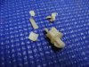
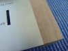
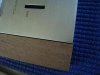
I am doing up the details on the sx-1250 I am working on and I noticed that the corner blocks were not sitting flush to the faceplate. I have had this trouble before on other sets and really not followed up on it. Anyway I attached some thumbs.

The corner blocks attach to those angles which are nestled into the extruded faceplate top and bottom flanges. They are held with a pressed dimple and that creates the friction fit to the slotted flange. I used a large slotted screwdriver and punched the dimpled, corner block angle further into the slot. Now the Walnut corner block sits flush to the faceplate.

I had the faceplate completely disassembled. I mean the glass, function selector panel and the trim around the dial window. I had the faceplate on its face on a piece of Yoga mat and the one end up against a clamped wood block. This protected the faceplate from collateral damage and I’m telling you, it’s not hard to mess these faceplates up. It doesn’t take much to set the walnut corner block angles once you have the plate secured and protected.

This is the little detail stuff I really like working on.
 

Attachments

  • sx1250 corner blocks 7.jpg
    sx1250 corner blocks 7.jpg
    48.3 KB · Views: 46
  • sx1250 corner blocks 6.jpg
    sx1250 corner blocks 6.jpg
    50 KB · Views: 49
  • sx1250 corner blocks 5.jpg
    sx1250 corner blocks 5.jpg
    36 KB · Views: 46
  • sx1250 corner blocks 1.jpg
    sx1250 corner blocks 1.jpg
    43.9 KB · Views: 62
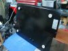
I cleaned and repainted the bottom cover. It had “Large filter cap poop on it”. I did both sides and replaced the felt foot pads with new. I bought the pads from Lowes and used a gasket punch to make the center hole. The pads are slightly bigger so I trimmed the sides with a xacto knife, which took a few minutes.

attachment.php
 

Attachments

  • sx-1250 bottom cover 3.jpg
    sx-1250 bottom cover 3.jpg
    56.2 KB · Views: 315
  • sx-1250 bottom cover 4.jpg
    sx-1250 bottom cover 4.jpg
    69.3 KB · Views: 53
Last edited:
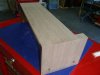
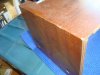
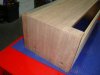
I finished re-veneering the 1250 case top this afternoon. I think I’m going to put a clear satin finish on it. I‘m still waiting for the (I hope) final Mouser order and I can get her up-and running.

attachment.php
 

Attachments

  • sx-1250 top case.jpg
    sx-1250 top case.jpg
    57.9 KB · Views: 236
  • sx-1250t top cover before 4.jpg
    sx-1250t top cover before 4.jpg
    88.4 KB · Views: 46
  • sx-1250t top cover before 3.jpg
    sx-1250t top cover before 3.jpg
    65.5 KB · Views: 39
  • sx-1250t top cover before 2.jpg
    sx-1250t top cover before 2.jpg
    88.7 KB · Views: 44
  • sx-1250t top cover before 1.jpg
    sx-1250t top cover before 1.jpg
    78.2 KB · Views: 62
Last edited:
I have the front face plate, corner blocks and top cover ready for final sanding and finish. It took a few hours to make sure all the parts line up and fit without gaps. Lot’s of fine tuning. It should look and fit better than the factory. I hope it will look a little better with all the hours I put into it.

attachment.php
 

Attachments

  • assy 2.jpg
    assy 2.jpg
    76.3 KB · Views: 221
  • assy 3.jpg
    assy 3.jpg
    62.2 KB · Views: 40
I did a boneheaded mistake and had contacted two different sellers at the same time and got mixed up when making the offer for a “Buy it now”. I ended up paying too much for the worst of the two sets. I really shouldn’t tell you guy’s my dumb ass attacks but I know that’s how we learn. It’s not that bad, the set will be in top shape and tsd71, your spot on, I plan on keeping it.
 
“Tickling the Dragon”

I put this together and it may be a little over-kill. If it is incorrect I will delete it. Do not use this unless it is vetted by an experienced Tech.

The start-up procedure for the sx-1250 after repair/restoration of the output boards and stabilizer board “Tickling the Dragon”:

1) Both Out-put boards (AWH-048) unplugged. Volume to zero or min.
2) Stabilizer board (AWR-106) plugged in.
3) Set connected to the DBT with a 100 watt bulb.
4) Flip the switch and check/adjust Stabilizer board (AWR-106) rails to +65 - -65 volts. Make sure voltages respond to adjustments and hold steady.
5) Power down.
6) Plug in one output board.
7) Turn VR2 on Out-put boards (AWH-048) fully CCW.
8) Power-up and check/adjust the Output board (AWH-048) trim pots VR1 for 0 volts and VR2 for 100mv. Make sure voltages respond to adjustments and hold steady.
9) Back off VR2 CCW
10) Power down and connect the (second) Output board (AWH-048).
11) Power-up and check/adjust the (second) Output board (AWH-048) trim pots VR1 for 0 volts and VR2 for 100mv. Make sure voltages respond to adjustments and hold steady.
12) Back off VR2 CCW
13) Replace the 100 watt bulb with a 150 watt bulb.
14) Repeat steps 7 and 10, checking for the Soft Start and Protect relays to energize.
15) Back off both VR2 pots CCW on both Output board’s (AWH-048).
16) Power down.
17) Remove DBT and operate set at full line voltage.
18) Make final adjustments to the Stabilizer board (AWR-106) set rails to +65 - -65 volts.
19) Make final adjustments to both Output board’s (AWH-048) trim pots VR1 for 0 volts and VR2 for 100mv.
20) Listen to Rush 2112.
 
Last edited:
Back
Top Bottom