• The move to the new server is done. There are some software and database maintenance updates in process. This has us passing the hat around to help out. We appreciate any donations. Seriously, even a dollar helps. The payment page may be found here - https://www.audiokarma.org/support.html

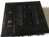
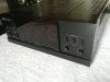
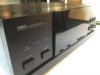
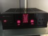
Another M-80 Restoration Project

Mine is serial 9141. It already had the 0.022's installed on the power board. It was also saddled with the 17 amp 2SA1216's and 2SC2922's. I'll do the PS caps this weekend, and I'm still continuing the WIMA before and after... Still deciding on the listening tests to keep the film and foils... I even have some MKM's which are mixed film and have a some interesting tones about them.
 
Last edited:
More pix please. I like this vintage of Japanese audio..........same vintage as my Sansui B-2101-2.....Massive powered/low distortion (relatively rare) gems.
 
Now find them on the schematic..
Oh don't get me wrong, I get it... But to have voltage references that will help someone out there diagnose a board issue is always good to have. Most of the ones you find out there on web don't have enough detail to see. And the high-res one you referenced, doesn't contain the entire amp.
 
Last edited:
Hint :You will have better luck with the M-85 scat.
Hey, on another interesting note, the M-5000 seems to utilize the same size as orginal 33000uf 63v needed for replacement, although screw terminal. (which doesn't matter) I'm going to need to get with a service center in Dallas to see if I can get my hands on a couple of them... I'm confident that the Nichicon NR's will do a fine job, but I'm looking for options.
 
Hey, on another interesting note, the M-5000 seems to utilize the same size as orginal 33000uf 63v needed for replacement, although screw terminal. (which doesn't matter) I'm going to need to get with a service center in Dallas to see if I can get my hands on a couple of them... I'm confident that the Nichicon NR's will do a fine job, but I'm looking for options.
I'd be curious as well.
 
As rework continued today, one of the experiences I found when I removed the power boards, was that each of the pairings of finals in both the channel outputs and the voltage regulation circuit, were different lots and most disturbing, the rank. The outputs on the left were a rank of P and the right was Y, and the voltage pairs were one side 2SC2773/2SA1169 and the other 2SC2922/2SA1216, both of greatly different rank. B&D was kind enough to match 2 pairs of 2SC2922/2SA1216 Y's to match the one side, which leaves me with a matched set of 8 2SC2773/2SA1169 in both lot and rank to match outputs on both R&L sides after rework. I can only conclude that either no one was paying attention at the factory, or, this unit went through repair and the tech saddled them like that.

As a sidebar, I get asked at times, how tight do you place the screws, (and yes there is a torque spec) and for the MT-200 it is 7 inch-pounds. Anything over 10~12 inch-pounds yields diminishing returns, and will distort the package. SanKen recommends Dow SC-102 compound for use with these devices.

 
Last edited:
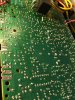
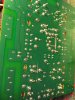
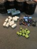
Completion of rework of the main board coming to a close. New solder throughout. Selected choices of WIMA's done. Used FKP-2 in the ZDR circuit, MKM-4's for their unique construction, (metallized mixed film) stability to high heat, as well as a unique signature to the audio. (brighter than Mylar) New 5% bleeders throughout.

IMG_0144.JPG IMG_0146.JPGIMG_0148.JPG
 
Last edited:
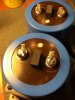
Standard insulated ring terminals gave themselves as donors to be made into tabs for cap mounting. (does that void the warranty? ;)) Re-purposed bump stops from the old caps to keep the screws from getting bounced into the board.
IMG_0149.JPG IMG_0150.JPG
 
Last edited:
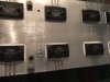
Prepping the heat sinks with new mica and thermal compound. One side raw, and the other finished and cleaned after removal of excess. I cringe at times when I read that folks are using very aggressive agents to clean with, and the correct solvent to use on output devices and thermal compound cleanup should be petroleum based naphthalates, like turpentine, white mineral spirits or naphtha. Complete reassembly and testing happens this weekend. (and I'm ready!)

IMG_015.JPGIMG_0153[515].JPG
 
Last edited:
Completed the assembly, set the bias, and got to listen today! It's punch has returned with the new PS tank circuit caps. And while the originals still met the capacitance tests, it failed ESR on the 47k's. There is something to be said about having fresh Al electrolytics, and ditching 30 year old caps. The M-80's 2.9dB of dynamic headroom requires that new PS caps are in place.

On a note about safety, and I know it's not spoken of very often here, but for those like me who have R models (general model w/variable voltage settings) most don't realize that you can have line voltage in the transformer and potential if you get a ground around the chassis, depending on the way you plugged it into the outlet, even without the power switch on. I did do a cord change to facilitate a UL approved wide-blade neutral to always prevent this, and I don't ever see this unit going out of the US.

I'll take some final pics of the completed unit sometime soon, but as for now, I'm enjoying the tunes too much to want to bust it down today!
 
Last edited:
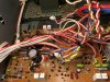
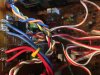
When doing your restorations, a couple of things to keep in mind, and that is good solder joints are required for low THD and IMD, and if your amp doesn't meet advertised THD specs, start with a meticulous inspection of all solder joints. When doing your cable management, especially when dealing with AC leads from transformers, as best as possible, cross other cables at right angles, and never bind them in bundles with rail feeds or output cables. Don't bind rail voltage to your input cables.
IMG_0154.JPG IMG_0155.JPG IMG_0165.JPG IMG_0168.JPG IMG_0170.JPG IMG_0171.JPG IMG_0173.JPG IMG_0174.JPG IMG_0175.JPG IMG_0178.JPG
 
Last edited:
Back
Top Bottom