You are using an out of date browser. It may not display this or other websites correctly.
You should upgrade or use an alternative browser.
You should upgrade or use an alternative browser.
Another Pioneer SX-434 Repair Thread
- Thread starter <Sc00ter>
- Start date

I just checked the schematic and your headphone jack signal goes through the output transistors so I'd focus on cleaning the speaker switches to clear up the distortion issue. On higher power receivers, the headphone jack signal may come off the pre-amp or something like that but the 434 doesn't seem to work that way. On those receivers, the headphone sounding good while the speakers don't could point to the output transistors but I don't think so on yours.

The outputs may be damaged. The ability to pass low current with minimal distortion and then badly distort when approaching the rated collector current is a failure mode that I've experienced before. If you can still get them, the MJE15031G/MJE15030G work out as decent replacements.

<Sc00ter>
New Member
Yes, Deoxit D5 and F5. Pots are clean and clear.Have you cleaned all the switches and pots yet?
<Sc00ter>
New Member
Double checked the switches and pots. They seem good. One thing i noticed was taking voltage readings on the output transistors and the base of Q22 is reading -.34v while the other three (Q20,21,23) all show +/- .65v. All other readings between both sides of the amp are about the same.
Is that enough disparity to point to an issue on that end of the AF board? Q14 and 18 seem to be involved in that region. Since all those were just replaced and the bad audio persists, it made me think it shouldn't be related but seeing that voltage difference made me wonder if something upstream is in fact an issue.
Is that enough disparity to point to an issue on that end of the AF board? Q14 and 18 seem to be involved in that region. Since all those were just replaced and the bad audio persists, it made me think it shouldn't be related but seeing that voltage difference made me wonder if something upstream is in fact an issue.
<Sc00ter>
New Member
I built a signal probe tonight and poked around and found it interesting. I'll admit I'm now in deeper waters than I'm confident in so I could use a little more guidance.
The signal at Q5 is good and clean. From Q10 and beyond it is ugly. Between there is where I could use some more help. From what I can discipher, the signal goes to the Treble and Bass pots next (VR3a, VR4a). Those sounded clean to me as well. After those, I'm a little lost but by the time it gets to Q10 it's crusty.
Is this as simple as swapping out Q10 in hopes that I got a dud from Mouser?
The signal at Q5 is good and clean. From Q10 and beyond it is ugly. Between there is where I could use some more help. From what I can discipher, the signal goes to the Treble and Bass pots next (VR3a, VR4a). Those sounded clean to me as well. After those, I'm a little lost but by the time it gets to Q10 it's crusty.
Is this as simple as swapping out Q10 in hopes that I got a dud from Mouser?
Attachments
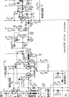
Can you look at the signal with your scope and maybe post some pictures. Components affect each other so finding where the noise starts doesn't always tell you the source of it. Have you swapped out Q16 and 17? From your list earlier it looked like you didn't. They should be replaced with complements of whatever you replaced Q 18-19 with. Have you replaced all the transistors on the AF board now?
<Sc00ter>
New Member
Yep. Can do. Every transistor on the AF and PS boards have been replaced with items from the approved list.Can you look at the signal with your scope and maybe post some pictures. Components affect each other so finding where the noise starts doesn't always tell you the source of it. Have you swapped out Q16 and 17? From your list earlier it looked like you didn't. They should be replaced with complements of whatever you replaced Q 18-19 with. Have you replaced all the transistors on the AF board now?
So just to confirm, Q16-19 should be complementary pairs. Did you use KSA-992 and KSC-1845 for those? How about the output transistors? Which part numbers did you use? Sorry if I missed that from earlier if you posted it. Just want to make sure you used complementary pairs.
The voltage issue on the base of Q22 could be something. Since you're seeing distortion at Q10 it could be something in that channel is throwing the whole amp section off but since you're seeing the voltage discrepancy only at one of the outputs, I'd start looking closer to there than back at Q10, which you might expect to affect both output transistors. Some scope pics might help here.
The voltage issue on the base of Q22 could be something. Since you're seeing distortion at Q10 it could be something in that channel is throwing the whole amp section off but since you're seeing the voltage discrepancy only at one of the outputs, I'd start looking closer to there than back at Q10, which you might expect to affect both output transistors. Some scope pics might help here.

Take a good look at the Emitter resistor on Q22 (R85).
Using your signal probe, probe from the volume pot output thru Q10 output. Check input signal and output signal on all resistors, and caps in line between Volume pot and Q10.
Using your signal probe, probe from the volume pot output thru Q10 output. Check input signal and output signal on all resistors, and caps in line between Volume pot and Q10.
<Sc00ter>
New Member
Hey Brian, Here's the list of parts I used for the transistors:So just to confirm, Q16-19 should be complementary pairs. Did you use KSA-992 and KSC-1845 for those? How about the output transistors? Which part numbers did you use? Sorry if I missed that from earlier if you posted it. Just want to make sure you used complementary pairs.
AWK-034 Q10 2SA725=KSA992FBU
AWK-034 Q11 2SA725=KSA992FBU
AWK-034 Q12 2SA725=KSA992FBU
AWK-034 Q13 2SA725=KSA992FBU
AWK-034 Q14 2SC1318=KSC2690AYS
AWK-034 Q15 2SC1318=KSC2690AYS
AWK-034 Q16 2SC1318=KSC2690AYS
AWK-034 Q17 2SC1318=KSC2690AYS
AWK-034 Q18 2SA720R=KSA1013YTA
AWK-034 Q19 3SA720R=KSA1013YTA
AWK-034 Q20 2SD313D=KSC2073TU
AWK-034 Q21 2SD313D=KSC2073TU
AWK-034 Q22 2SB507D=KSA940TU
AWK-034 Q23 2SB507D=KSA940TU
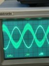
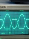
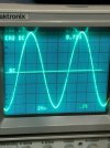
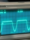
1k Sine Wave, Into Aux Input left, Volume up to roughly 9:00.Some scope pics might help here.
Image 1 Volume Pot Wiper Output
Image 2 Q21 Base (For Reference)
Image 3 Q22 Base (Bad News)
Emitter images followed the same pattern. Q21+23 in good shape, 20+22 bad.
Attachments

Last edited:
<Sc00ter>
New Member
Took it out, looked good, tested good. Put back in since I don't have replacements on hand. For testing purposes, can I replace with a 1/4 or 1/2Watt version if I keep the volume low or is that risky with anything less than the full 2Watt version?Take a good look at the Emitter resistor on Q22 (R85).
<Sc00ter>
New Member
Here are a couple screen shots of my progress so far. I'm WAY out of my league here and getting a little discouraged but this is how we learn, right? Talk me off the ledge folks. 
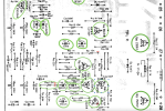
Image 1: Schematic area of interest. If audio signal roughly flows from lower numbered components to higher and roughly top down across the board, then this is the area where the signal goes from clean to distorted. If however, that's not how these circuits work, then disregard. I can't seem to get my scope to read any sine wave on Q5 or Q6 but my audio probe tells me that the signal seems ok on those.
Image 2: Just a reference for what's been replaced so far. And a reminder, this distortion existed before starting this project and hasn't changed with these replacements. So I'm still thinking it's something outside of what I've replaced so far.
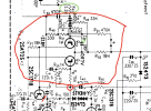
Image 3: Zoomed into the area that has taken the most attention so far.
Note: I rotated the board layout images for myself to match its orientation to what's in front of me.
Thanks again for all your insights fellas. It means alot for a life long learner like myself.
Image 1: Schematic area of interest. If audio signal roughly flows from lower numbered components to higher and roughly top down across the board, then this is the area where the signal goes from clean to distorted. If however, that's not how these circuits work, then disregard. I can't seem to get my scope to read any sine wave on Q5 or Q6 but my audio probe tells me that the signal seems ok on those.
Image 2: Just a reference for what's been replaced so far. And a reminder, this distortion existed before starting this project and hasn't changed with these replacements. So I'm still thinking it's something outside of what I've replaced so far.
Image 3: Zoomed into the area that has taken the most attention so far.
Note: I rotated the board layout images for myself to match its orientation to what's in front of me.
Thanks again for all your insights fellas. It means alot for a life long learner like myself.
Attachments

Ok, I have a theory. the top half of the input to the output transistors isn't there. That indicates a problem with the transistor that feeds it or the bias. I think it may be because of your transistor choices.
KSA1013YTA is a TO-92L case transistor that you used for Q18-19
KSC2690AYS is a TO-126 case transistor that you used for Q16-17. Can you confirm that?
Those two probably won't work well together. Your drivers should be complementary pairs. The complement to KSA1013YTA should be KSC2383YTA. I'd use that combo rather than finding complements to the 2690 here. I'd probably replace the other 2690's you put in as well but it may work with them.
Edit: Looking at the schematic, I'd replace all the KSC2690's with KSC2383's. I think Q14 may be affecting the bias which might be the reason half your sine wave is missing. But using non-complementary drivers will probably cause you some problems too.
KSA1013YTA is a TO-92L case transistor that you used for Q18-19
KSC2690AYS is a TO-126 case transistor that you used for Q16-17. Can you confirm that?
Those two probably won't work well together. Your drivers should be complementary pairs. The complement to KSA1013YTA should be KSC2383YTA. I'd use that combo rather than finding complements to the 2690 here. I'd probably replace the other 2690's you put in as well but it may work with them.
Edit: Looking at the schematic, I'd replace all the KSC2690's with KSC2383's. I think Q14 may be affecting the bias which might be the reason half your sine wave is missing. But using non-complementary drivers will probably cause you some problems too.
Last edited:
If those changes don't fix it, I think we at least have a direction. Also check D1 & D3 and all the resistors around them while you're in there. Those are where the biasing happens and having half your sine wave missing is a great clue there's a problem there.
D1 looks like a 3 diode package and some multimeters will have trouble checking those. It may look open even if it's good so might be easier to check it in circuit with the power on to check the voltage drop.
D1 looks like a 3 diode package and some multimeters will have trouble checking those. It may look open even if it's good so might be easier to check it in circuit with the power on to check the voltage drop.
<Sc00ter>
New Member
Les, That made our first new result! R73 measured at 33k! Once replaced I'm getting a whole new set of readings on just about everywhere. I'm going to take some time measuring and will update you all with the results. But at first look/listen, we just made great progress! Thank you.
@Brian1970. Depending on these results, I'll make an order on making better matched pairs of transistors. However, it should be noted that I chose all these components based on the approved Pioneer Parts List Doc on this forum. So if those are not good matches, we should ask for that to be updated.
Onward and Upward!
@Brian1970. Depending on these results, I'll make an order on making better matched pairs of transistors. However, it should be noted that I chose all these components based on the approved Pioneer Parts List Doc on this forum. So if those are not good matches, we should ask for that to be updated.
Onward and Upward!
Nice! I think you've got it. The stereo may work with those transistors in it. One channel seems to be. It's not that the list is wrong. It's just that you have to also look at the application they're being used in. Since your drivers transistors (and outputs) should be complementary pairs, that's why you shouldn't just pick any old transistor off the list. You want to have about the same amount of gain on those driver pairs and output pairs. I'm guessing with the ones you have in there, you won't. I'd be interested to see how it affects distortion but if you don't have the equipment to measure that, it's best to just go with parts that are made to work together. Your outputs are complementary so you're good there.Les, That made our first new result! R73 measured at 33k! Once replaced I'm getting a whole new set of readings on just about everywhere. I'm going to take some time measuring and will update you all with the results. But at first look/listen, we just made great progress! Thank you.
@Brian1970. Depending on these results, I'll make an order on making better matched pairs of transistors. However, it should be noted that I chose all these components based on the approved Pioneer Parts List Doc on this forum. So if those are not good matches, we should ask for that to be updated.
Onward and Upward!

Yes, in this case, 33K ohms pretty much gives the same result as an open.Les, That made our first new result! R73 measured at 33k!
Good work!

<Sc00ter>
New Member
Ok friends, here are some measurements and scope images of where I'm at. Still have dummy loads on the speaker terminals but the headphone output sounds fantastic.
Just to go back a bit I did measure D1=1.5v, D2=1.6v, D3=0.6v, D4=0.7v. It's a good thing D1&2 are ok because I've heard they are unobtainable.
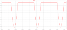
In the images below trace 1 is as close to the volume wiper i could get a hold of (C17/18) combined with the matching speaker output. I'm guessing the first trace is soft/blurry because its looking at a very low level signal at 10mv. Is that normal? Volume at 9:00.
But, the next image is showing what happens as I get the volume to 50% or above. The Volume signal looks good but the outputs obviously in full clipping meltdown by then. My Glow Bulb Tester is also lighting up pretty good by then. Is this behavior normal or should I start tracking down where that clipping is being introduced? For reference, back in the day I never felt the need to turn this up and louder than about 9 or 10:00 so that's still plenty of volume for my situation. Just curious how wild one can get before hurting something again.
Just to go back a bit I did measure D1=1.5v, D2=1.6v, D3=0.6v, D4=0.7v. It's a good thing D1&2 are ok because I've heard they are unobtainable.
In the images below trace 1 is as close to the volume wiper i could get a hold of (C17/18) combined with the matching speaker output. I'm guessing the first trace is soft/blurry because its looking at a very low level signal at 10mv. Is that normal? Volume at 9:00.
But, the next image is showing what happens as I get the volume to 50% or above. The Volume signal looks good but the outputs obviously in full clipping meltdown by then. My Glow Bulb Tester is also lighting up pretty good by then. Is this behavior normal or should I start tracking down where that clipping is being introduced? For reference, back in the day I never felt the need to turn this up and louder than about 9 or 10:00 so that's still plenty of volume for my situation. Just curious how wild one can get before hurting something again.