• The move to the new server is done. There are some software and database maintenance updates in process. This has us passing the hat around to help out. We appreciate any donations. Seriously, even a dollar helps. The payment page may be found here - https://www.audiokarma.org/support.html

Another Rowe 4359 amp rebuild

nerdorama

AK member
Subscriber
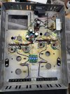
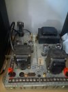
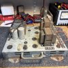
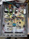
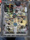
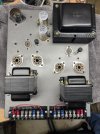
It isn't really a Rowe any more as it will be 6L6GB or earlier. I will also be using IBBA and EFB boards. I have the audio circuits nearly complete except for installing the PC boards. The transformers will be about the last things to install just to keep the weight down while I do the other wiring. Have made decent progress so far. Not sure how the transformers will work out. I also added some Cinch barrier blocks for the secondary connections and wiring to the binding posts which I installed where the 70V terminals were originally. I patched/filled quite a few openings that I don't need. Had to glue in some thin aluminum under the larger holes so the epoxy and bondo had some support. Trying to make a bit of progress each day but not sure how soon I will be ready for power up.
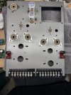
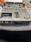
Rowe top deck.jpgRowe power entry.jpgRowe wiring.jpg

I am also altering the 12AX7 circuits a bit per Dave Gillespie's Fisher 400 mods.
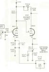
Fisher 400 12AX7 circuit.jpg
 
Register to hide this ad
just make sure its got enough voltage swing, a 6L6GB needs roughly double what the 7868/7591 family needed. Probably will be OK with the modification to remove the noose but worth confirming. Possibly will need higher supply voltage to get the swing.
 
The 6L6GB/C data sheet for 360V plate and 270V screen shows a bias voltage of -22.5. This is only a few volts more than the 7868/7591 requires. The Rowe schematic shows a fixed grid bias voltage of 18.5V. Seems like it should be ok. The Fisher 400 schematic from DaveG's EFB thread shows -15V. Still not too far from the -22.5V. Anyway, I'm going to give it a run and see what happens.
 
Finally we will see a project to proceed.
Are you going to use a 70v winding for a feedback?
My Rowe is ready and is sitting in a starting block.
Looking forward for next steps. Thank you.20260814_110226.jpg
 
I’ll measure the 70v winding and see if I think it can be used for feedback. It has to be electrically symmetrical on each side relative to the CT. But, it may have a too high voltage to use for cathode feedback. We’ll see.
 
make sure its got the same sort of open loop response as the speaker winding. I ran into that on my Rauland amps. Those have a dedicated feedback winding, plus the speaker secondary. Testing had the response falling off a cliff and I couldn't figure out why. At some point I measured the response across the feedback winding and found it was dead flat while the speakers were falling. In open loop mode the feedback winding had a huge rising response that the speaker winding did not so the response wasn't useful. Ended up fixing it by abandoning the feedback winding and taking it from the speaker secondary.
 
Understand. A cathode feedback winding has to have a good freq response and be balanced between the halves. Using the speaker output on this amp probably isn't realistic with the plethora of output taps. I'll just start with the normal global feedback and see what happens.
 
this one wasn't cathode feedback, just a regular old 2 wire winding, ground at one end, up to the first tube on the other end. Still amazing how bad it performed. The transforrmers in those amps aren't amazing but the feedback winding is way worse than the speaker windings.
 
Looking Great!
I'll be watching this build with great interest as well- I too have a scuzzy Rowe waiting on the bench I'm wading towards. My intention was to go the "test mule" route first, to try to finally get answers to some of the common concerns/questions that have always popped up on these- about how well a 12AX7 circuit will drive a 6L6 family, and just how good these transformers actually are. Using the different tap combinations I'd love to experiment with other output tubes- maybe even some sweep tubes. I'm not far enough along in my learning to play with output tube cathode feedback, and the 70V winding looks sketchy for feedback, but with standard speaker tap feedback (+plate?) I'm curious how they will do. I really like that direct coupled 12AX7 with adjustable cathodyne- looks promising. Thanks for pointing to Dave's thread on the Fisher 400. I can't wait to read up on that and try my hand at the screen EFB. Being a test mule I was tempted to cobble in a third tube to try the long tail pair thing, but maybe it's not needed- anxious to hear how it works out.

Your chassis looks great with all of those holes filled- You have probably been doing this for awhile- how does the epoxy and bondo filler hold up over time? Does it crack with thermal cycling? Any tips? Be sure to throw out some schematic sketches as you go along!

s-l1600a.jpg
 
You can drive it, mostly its a question of open loop gain v feedback level v input sensitivity. My Rauland amps are more or less this circuit with an extra gain stage. 12ax7 is two voltage gain stages, 6av6 (half a 12ax7) is the splitter. Half of the 12ax7 is in the loop, half is not, so basically imagine this amp with a half a 12ax7 between the input jack and the power amp.

Thats an el34 amp but probably needs more signal than this would with a 6l6 class at under 400v. It runs north of 650v on the plate. Offhand I want to say its biased around -40v.

12.8db of global feedback, and about 0.6v to make full power after doing stuff to drop the gain at the first stage. If I bypass it, its closer to 4v to make full power.

If it just doesn't have enough gain, a 6u8 or other triode pentode will certainly get it done with a single 9 pin socket.
 
how does the epoxy and bondo filler hold up over time?
The bondo isn't so good. It's too soft. The JB Weld is better since it gets really hard and can be drilled. Either way the larger holes need some sort of backing material. I cut some thin aluminum from a pop can, flattened it out, and epoxied it under the openings. I clamped it with a wood block and some wax paper to keep it flat until the epoxy set up.

One detail I'm not sure I mentioned. I ground off the rivets holding the flanged feed onto the chassis. My intent is to reinstall them inwards for a place to mount some amplifier feet. The angle on the long side I had to shorten a bit on each end to clear the folds in the chassis corners and still line up with the rivet holes for bolting back on.
 
Finished the wiring, did some preliminary voltage checks and adjustmets to the IBBA and EFB boards, and tested out a set of tubes. Got the system slowly up to full AC voltage with the variac. All voltages ok but slightly low. The 5881's that I had are biased at 25mA which is probably a bit low but should work for starters. I assume if I run the bias current up more then the B+ and screen voltages will drop even more. I have a 5AR4 that I might install and see where that gets me on the voltages. Might be a bit too high then but maybe would be close to my original target. Done for today.

The binding posts on each side are wired to terminals 7 & 8. 1 thru 6 match the original terminal layout. I made jumpers so I can connect the binding posts to whichever impedance combination I want to use. I found some 8 terminal Cinch barrier blocks that fit the opening and some marker sheets that bolt in under the strip.

Rowe wiring complete..jpgRowe top and ready for tubes.jpgRowe with tubes.jpeg
 
Got a couple of prelimary measurements this morning. Using a 5U4GB rectifier and about 10dB feedback, I'm seeing about 14.7W at the tiniest sign of clipping at 1kHz. Switched to a 5AR4 and got a bit more voltage but the clipping only went to 15W. Was expecting closer to 20W but maybe this is where I will end up. Need more measurements to see if something else is up. I'll want to know what the 5881 grid drive voltage is from the PI. It's possible the phase splitter is pooping out first. Have to go mow the grass now.
 
Last edited:
The transformers sure turned out nice- very nice and all new looking with that brass hardware. The barrier blocks look great, and a very nice neat layout underneath.

(Following the program from the cheap seats-) If I follow your secondary connections, 70V taps tied off, you are running speakers with E1 and E3 (floating), turns ratio = 29 for 6.7K @ 8 ohms. That seems to match the RCA 5881 datasheet values for class AB1 at the 360V/270V/-22.5V with 44mA@ (with 26W output at the plate). Are those the voltages you are shooting for? Does seem quite low given the 80% of 26W approximation. Open loop now, but feedback from taps E1 and E4 (grounded). Curious to hear how that cathodyne is working out. Great work!
 
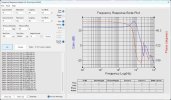
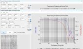
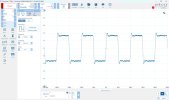
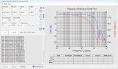
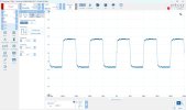
Got a bit of testing done this afternoon. These output transformers aren't too shabby. I'm using about 10 or 10.5dB of feedback. I've tried a few different values of phase advance cap. The initial FR with no cap had a pretty good peak of about 6-7dB in the 70-80kHz range. I was able to flatten that with 500pF but that still left a pretty good rising edge peak on a 10k square wave. 750p flatten the 10k rising edge and rolled of the FR but was still -3dB around 70kHz. I can probably live with that but would like to see if I can smooth things out a bit more. Anyway, a reasonably encouraging session.

BTW, these were all made with the test resistor connected across E1 and E3 for about a 6700 ohm reflected load. Initially I had the 5881's biased at 28ma but I increased that to initially 35mA and now 40mA. This also increased the 1kHz power at clipping to about 18-19W which is closer to what I expected.

FR with feedback resistor only.
Rowe FR 5.1k fdbk only.jpg

With 500p added
Rowe FR 5.1k_500p fdbk 35mA bias.jpgRowe 10kHz square 5.1k_500p 35mA bias.jpg

increased to 750p
Rowe FR 5.1k_750p fdbk 35mA bias.jpgRowe 10kHz square 5.1k_750p 35mA bias.jpg

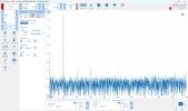
This is a 1W 1kHz THD run. Not too bad.
Rowe THD 1W 5.1k_750p fdbk 35mA bias.jpg
 
Last edited:
If I follow your secondary connections, 70V taps tied off
Yes, I left them open but should probably put a resistor load on them to keep any possible noise issues from happening. Guess I'll measure the voltage across them at this amp's full power of 18ish watts.

So far the results are better, in most details, than I was expecting. Some of the prior threads in AK about these amps made me think that the transformers were a bit mediocre but I'm seeing quite good results so far.
 
Thought I might comment on the EFB board. So far I can't say how it affects THD and power performance but I makes for easy scaling of the screen voltage via a divider on the board AND it also sources the bias voltage to the IBBA board. Initially I couldn't get the bias current over 35mA but the potentiometer on the EFB let me readily readjust the raw voltage and voila. Thanks to @ncwalz for sharing his board designs.
 
may be a case of the transformers are OK at lower feedback levels but not so good at high levels. Some less than stellar iron develops stability problems with too much feedback.
 
Understand. I'm going to try some higher levels of feedback and see what happens. If it stays stable at 12-15dB that should be ok.
 
Back
Top Bottom