• The move to the new server is done. There are some software and database maintenance updates in process. This has us passing the hat around to help out. We appreciate any donations. Seriously, even a dollar helps. The payment page may be found here - https://www.audiokarma.org/support.html

Another Scott 222C

Status
Not open for further replies.
Hi Brian,

Are you telling me that you can access the HH Scott forum? Try clicking the link at the bottom of the page that says, "Join Scott Forum". That is where I am talking about. I have gotten emails from members too. But the forum doesn't seem to work. If you get it to work, please let me know.

Here is a link to the "Secure Forum" http://secureforum.com/~vhhscott

Emails to Lee Shuster have gone unanswered.

Thanks,

I see now what you are talking about. I am a member of the e-lists. The 'secure forum' link doesn't work for me, either- I don't know what the difference is. Maybe... the forums work directly on the site and the e-lists are emailed to you. I found the forum layout to be cumbersome so I appreciate getting the emails.
Brian
 
Thanks for taking the time to reply. I was hoping the secure forum was back up working. "We should be so lucky!" I miss it very much.
 
Thanks for taking the time to reply. I was hoping the secure forum was back up working. "We should be so lucky!" I miss it very much.

Is there any difference between the two as far as the information contained within?
 
That is a good question. I never tried the e-list. I really liked the forum. From my perspective, it was rather simple. Tuner section, amp section, owner showcase etc.

I will go to the site again and investigate the e-list thing...
 
Don't remember exactly but doesn't the 222C have bias pots? Or are they AC balance? If it has bias pots, I think you can get by with adjusting for the correct idling current. (Trivia question: In transistors, didn't they call that the quiescent current?)

After a closer look, those 330K's are coming from the AC Balance pots; and the grid resistors are the correct value.

The late version 222C was like the LK48B and had 330K grid resistors and bias adjustments. But. . . not this one.

. . Falcon
 
Flash... Just got an email for Lee Shuster. He is doing well. Just very busy with work and family duties. I thanked him for all of the wonderful resources on the Scott site.
 
Just about done until the new tubes come in.

Ok,

I am just about done until the new tubes arrive. I can't really fit any more caps under the hood for the main power rail. So unless I buy a replacement Cap can I guess that is done for a while.

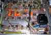
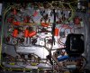
The last two orange drops are the .022uF in the upper left of the picture, and they seemed to be directly in my signal path if I traced those wires right! (Guess I coulda looked at the schematic) I could really tell a difference in the tone. Not sure is I like it or not yet, but, I will decide after more break in and after new tubes.

Ok, so I am really wondering if the Mallory 150's at the bottom of the pic are a mistake? They are polyester, which I hear can be bad for your tone, but I see a lot of people use these, and I wonder if they are the 'lemon drop' capacitors I see a few people talk about.

Any thoughts on any of this is welcome! I know a lot of this is subjective. Currently I turn the treble to half and the bass almost all the way up and the MP3 player has a 'rock' EQ chosen. That probably is a big U shaped eq curve heavy on the bass. The JBL stadiums have fairly good high end, even though they do not have the Titanium tweeter I prefer, instead using a laminate.

It does thump though! which is pretty cool for 24 watts on a good day.

Dan
 

Attachments

  • Scott 222C stage 4 rebuild AK.JPG
    Scott 222C stage 4 rebuild AK.JPG
    159.6 KB · Views: 108
  • Scott 222C stage 4 rebuild AK(2).JPG
    Scott 222C stage 4 rebuild AK(2).JPG
    174.2 KB · Views: 85
Yeah, that's one of those American Radionics that puked!

Good to see you replaced it.

I still see four 330K grid leak resistors in there. You'll probably want to change them out to 200K or 220K if you plan to run new production tubes. But, you may want to check on that with Jim McShane first. (300K is the max grid resistance for those power tubes in the RCA Tube Manual, and the new production tubes just aren't as robust as the vintage type).

. . Falcon

Now were applying this dubious theory to EL84/7189 based amplifiers???
 
Driving Miss JBL!

Ok, My biker babe wife keeps turning off the Scott so she can watch TV so I brought it into the man cave and hooked it up to my PA speakers!

Even though it seems an unlikely thing to do, I kept thinking these are my only horn loaded cabs, and I just had to hear this thing with Horns.

So, These are JBL Cabaret Series with 15" Drivers for the low end and Titanium drivers in those horns.

I have high end for days, even though the horns are 16 ohm and the woofers are 8 ohm. When the bass is pushing it is very clear throughout the house. But, being JBL, it is not a crisp bass, rather has that softer old school bass.

I got these cabs totally destroyed by some DJ type. I had to recone the speakers, replace the titanium drivers, and rebuild one of the crossovers. (Shoulda done both but I was actually not 100% sure on some of the values so I left the one that was good stock.)

Funny story about how I got them. Max wanted me to build him a pair of small cabinets and pay for the titanium drivers he had bought for them.

I got all excited and flew home, and whipped out a pair of real nice cabinets in like, an hour and a half! I delivered them to him triumphantly and he saw how little time it took me, and was like, I meant two pair!! I looked at him and realized my mistake and trudged home. The second pair took a day, had to get parts and I was no longer so excited. :banana::banana:

But when it was all said and done, I had a set of mains that are totally totable.


3154858077_d288b39b6e_b.jpg


http://www.flickr.com/photos/knifefighter/

 
So, where do I set the bias on this amp?

Now were applying this dubious theory to EL84/7189 based amplifiers???

Hi, so , where do I set the bias at on this amp?

I saw where it was worked out that the pot is a balance pot, and, it looks like a total network on that 7189 pin.

Dan
 
Now were applying this dubious theory to EL84/7189 based amplifiers???

Not really.

In a follow up reply I said:

After a closer look, those 330K's are coming from the AC Balance pots; and the grid resistors are the correct value.

The late version 222C was like the LK48B and had 330K grid resistors and bias adjustments. But. . . not this one.

. . Falcon

Why do you think Jim's theory on grid leak resistor values and new production tubes is unsound? I'm speculating that it's because you've never run into that issue on any of the hundreds of Scott and Fisher restorations you've done.

. . Falcon
 
Falcon

Hi Falcon,

hope you are following this thread now!

Got any idea on my question about bias on this one?

When I put the new 6p14p-eb tubes in this I think it would benefit from being properly set up.

Should I bug Jim McShane on that one? Man, he is an encyclopedia of info isn't he!

Oh snap, I just realized some of you guys are hung over and a lot of people may be out of town. I'll put on my headphones

:music::music::music:


happy new years! For those who do not celebrate our calendar glad you woke up this morning! :D:D
 
Not really.

In a follow up reply I said:


Why do you think Jim's theory on grid leak resistor values and new production tubes is unsound? I'm speculating that it's because you've never run into that issue on any of the hundreds of Scott and Fisher restorations you've done.

. . Falcon

Well not to be brutal. But your follow up was inaccurate. Those pots are DC balance pots. They allow the balancing of each pair of output tubes. The 222C has no AC balance pots. It also has no provisions for a novice to measure and set the bias. The negative applied grid voltage is not the bias. It is simple a means to adjust the bias. You measure the bias either at the cathode or at the plate of the output tube.

As far as the grid resistor theory. I have never out and out said it would not help band-aid the problem with "some" modern production tubes that have excessive grid leakage. I simply think the modification leaves way to much information out. Simply changing this grid resistor value and asssociated cap value is half the story. I'm not going to spend countless hours argueing over it.
 
Hi, so , where do I set the bias at on this amp?

I saw where it was worked out that the pot is a balance pot, and, it looks like a total network on that 7189 pin.

Dan

The best you can do with the stock circuit 222C is to adjust the first dropping resistor off the bridge rectifier so that the first 12AX7 heater receives -44 VDC. Then center travel of and then equalize the applied negative voltage with the balance pots so that each tube in the pair get the same negative voltage. I perform all the above with the 5AR4 rectifier removed, then I fire up the amp and let it warm up and use my fluke meter setup to read current and shunt the plate supply from the center tap and get a round about reading (a bit low) of the current for each tube in the channel. Then adjust the balance pot to equalize each pair... Run of the mill cheap bargain bin meters will not live or accurately make this reading. This is also very dangerous for the novice since you are dealing with around 400V.....SO BEWARE.... I really do not like giving instruction like this on a open public forum because of the danger involved.

The proper current draw for the 222C is about 22 or 23ma per tube. With my Fluke doing the above proceedure if everything is working properly I should get about 20ma reading which will translate to the 22 to 23ma.

I almost always modify the 222C to allow complete testing and setting of the bias safely from above the chassis. But its a pretty complicated under taking for this amp.
 
Now were applying this dubious theory to EL84/7189 based amplifiers???

There is nothing the least bit dubious about it. Period.

The change to the grid resistors I recommend applies to the 7591 only.

The "information left out"?? It's been published MANY times. So to make you happy, I'll publish it again.

The lower grid resistor values do lower the gain of the previous stage slightly, because as you must know the grid resistor is effectively in parallel with the plate resistor of the preceding phase splitter stage.

It should be noted that low Rp and high Gm is very desirable in a concertina splitter, which is what the Fishers and Scotts (and others) use.

In Fisher gear, most of the time the 7591s were driven by a 12AX7 - the 330K stock grid resistor value was an attempt to make that possible, 12AX7s are hardly "robust" drivers. But even Fisher realized it wasn't the optimum, and in some models used a 12DW7/7247 in place of the 12AX7s - the "12AU7" section of the tube (with a near 2x increase in Gm and 1/6th the plate resistance versus a 12AX7) was used to drive the outputs. If I had a Fisher, I would replace the 12AX7 stage with the 12DW7 stage from other Fishers. The change to the 12AX7 driver was a bean counter's decision, not an audio engineer's decision.

FYI, the max grid resistor value spec'd for an EL84 in fixed bias is 300K (it's 1 meg in cathode/self bias). But I've found the new EL84s work fine with the 330Ks. And in your Scott 222C while indeed there are 330K resistors on either side of the DC balance pot, there is an additional 270K resistor from each of the 7189 tube grids to ground. This yields an effective grid resistance of roughly 150K. That works well with the stouter triode section of a 6GH8 or 6U8, which is much more muscular than the 12AX7 a la Fisher - and can handily drive the 150K load.

Is that enough info now, or do you need more? :scratch2:
 
Jim,

When are you going to get it? Your snide remarks and general nasty tone keeps this subject from moving forward... maybe staying over at AA where that kind of behavior is acceptable would be wise. You are welcome to your opinion as I am. You know you could learn something here also.

I stated above

"I have never out and out said it would not help band-aid the problem with "some" modern production tubes that have excessive grid leakage." (I should of added "or develop")

I completely understand the theory you are laying forth here. BUT IT IS INCOMPLETE.... and in my honest opinion (garnished from 100's units in the field) unneccesary... That is my Opinion and I absolutely have a right to it.

Your theory leads folks to believe that simply inserting this magical resistor/cap combo will fix the entire problem. IT WILL NOT and as your wonderful explanation states it brings more problems to the table in that it skews the gain of the previous stage pretty dramatically (try doing one channel some time it is indeed dramatic) which in turn changes the sonic and measured performance of the amplifier. Then factor in your blanket statement which leads to the above assumption that they need to be changed in Scott amplifiers and THEY ABSOLUTELY DO NOT. You know if the general public and the tube dealers would not except these loose tolerances that the tube manufacturer supply they would be forced into better quality control. What I find real interesting is some tube dealers defend rather then complain about the poor quality control.

The receivers in question also require the proper adjustment of the biasing of the output section which I find more important then the magical grid resistor/cap change. AND stating "Set it to XX negative volts is not accurate. Each quad of tubes requires a different XX negative volts to set the bias especially when dealing with the crude quality control of modern production tubes.... You know as well as I that the variance in the current draw per applied negative control grid, plate and screen voltage for these modern production tubes are huge in a lot of say 1000 tubes....they can vary by as much as 40%... This has more to do with the problems then the grid resistor value. I have also found both EH and JJ tubes do not perform long term unless you bias them below 30ma per tube in most amps. The higher the plate and screen voltage the lower the current needs to be.. Bias them higher and that grid leakage syndrome sets in pretty quick... THIS has been determined via tried and true field testing...

Between Paul Grzybek (Bizzie Bee) and myself we have countless 100's of these receivers out in the field without excessive modern production tube failure, Paul used and sold EH 7591 exclusively for years. Neither of us has ever changed this grid resistor and we have never experienced early failure beyond the now and then norm... Explain that to me? I guess were just lucky Heh! I believ Fisher Doc doesn't recommend it either..


Umm your 12AX7 versus 12DW7 theory doesn't wash with Fisher production history... the products that used the 12DW7 was nearly always used in products that were produced before and during the same time period as the products using a 12AX7. They stocked both tubes so bean counting could not have been an issue.... Heck they even were so anal about the sonic difference in tubes they stocked different brand 12AX7's and used different brands consistantly in different locations in the same product.... Mullards in the MPX section and Telefunkens in the phono, tone and driver circuit... I have also seen USA made fisher branded 12AX7's used in the MPX section of very late model receivers. They used a 12AX7 for the driver because they liked the Sonic character in that location would be the only logical conclusion. Besides in that day and age these tubes were pretty darn inexpensive... Heck Mark Deneen told me in 1975 he was paying $1.60 for Amperex made in holland 12AX7's for the Paragon 12 preamp........ how would of you like to have purchased a few thousand of those in 1975 for resale now!! I can only imagine in the quanities Fisher was buying they paid pennies for these tubes in the early 60's

So to answer your question. No it was not enough......
 
Got a schematic?

The best you can do with the stock circuit 222C is to adjust the first dropping resistor off the bridge rectifier so that the first 12AX7 heater receives -44 VDC. Then center travel of and then equalize the applied negative voltage with the balance pots so that each tube in the pair get the same negative voltage. I perform all the above with the 5AR4 rectifier removed, then I fire up the amp and let it warm up and use my fluke meter setup to read current and shunt the plate supply from the center tap and get a round about reading (a bit low) of the current for each tube in the channel. Then adjust the balance pot to equalize each pair... Run of the mill cheap bargain bin meters will not live or accurately make this reading. This is also very dangerous for the novice since you are dealing with around 400V.....SO BEWARE.... I really do not like giving instruction like this on a open public forum because of the danger involved.

The proper current draw for the 222C is about 22 or 23ma per tube. With my Fluke doing the above proceedure if everything is working properly I should get about 20ma reading which will translate to the 22 to 23ma.

I almost always modify the 222C to allow complete testing and setting of the bias safely from above the chassis. But its a pretty complicated under taking for this amp.

Thanks for the ideas - You don't happen to have a schematic for setting that bias safely from above the chassis do ya?

I am going to be faced with setting that up as soon as my NOS russian tubes arrive!
 
Passion Rocks

I think it is great to see two people so passionate about their love of tube amps.

You can't see a good discussion of grid resistors anywhere near where I live!

Dan
 
Thanks for the ideas - You don't happen to have a schematic for setting that bias safely from above the chassis do ya?

I am going to be faced with setting that up as soon as my NOS russian tubes arrive!


The 222C is basically a stripped down version of the 299B amplifier. Download the 299B amplifier schematic and follow its schematic for the changes to the bias adjust scheme. Then add a 10 ohm cathode resistor and test point (tip jacks work well) for each output tube. It sounds simple but it will require tons of rewiring especially the area around each 7189 output tube since scott used the cathode of each tube as a common ground point for various resistors which will have to be moved to a new ground point you provide. I can do it with my eyes closed no schematic required I've done it so many times.

Craig
 
Status
Not open for further replies.
Back
Top Bottom