• The move to the new server is done. There are some software and database maintenance updates in process. This has us passing the hat around to help out. We appreciate any donations. Seriously, even a dollar helps. The payment page may be found here - https://www.audiokarma.org/support.html

Anti-static point in New CD Laser

searchlight

New Member
Does anyone know of a good step-by-step guide that tells you how to remove the anti-static point in a laser assembly?

For example, my player uses a KSS-210a. Is there a guide that shows where the anti-static point is, and how to remove it?

Finally, I can't seem to find the answer to whether new lasers need to be calibrated or just installed where the old laser was attached.

Your kind feedback is appreciated.
 
Register to hide this ad
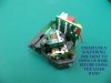
I assume you mean the short across the laser diode? If it's a blob of solder, all it usually takes is wiping a clean soldering iron across it. The blob should stick to the iron. If it doesn't, a little solder wick will take care of it. Ideally, it should be removed only after the pickup has been plugged in.

Early players generally require some adjustment, but anything made in the last 20 years is likely to be plug and play.


Thanks for the reply but so I understand don't you mean the blob of solder that is on the PCB that the techs refer to?
 
The KSS blocks are plug and play. No adjustments.

Here's a google search on the solder point.

Marc
 

Attachments

  • 210A_3.jpg
    210A_3.jpg
    35.6 KB · Views: 96
I think Tinman means that modern players using KSS optics are self-aligning. Older players will most likely need alignment touch-up.

On your optical assembly's flexible board, you'll see a semi circle-ish pad filled with solder, all by itself. That's the short point. Like everyone else says, just wipe your iron across it and the gap between the two pads will be revealed.
 
Back
Top Bottom