• The move to the new server is done. There are some software and database maintenance updates in process. This has us passing the hat around to help out. We appreciate any donations. Seriously, even a dollar helps. The payment page may be found here - https://www.audiokarma.org/support.html

Any Fisher expert techs in the PNW?

sbcrockett

AK Subscriber
Subscriber
Hey guys,

Not saying that I won't take up the challenge of going through my X-100-2 but before I post a detailed thread about my amp, I was wondering if there were any Fisher experts in the Seattle/Tacoma area? I'm relatively new to tube amps but learned a lot recapping, modifying and adjusting bias on my Scott LK72 a few weeks ago. I would like to try and do the same for the Fisher but I'm finding that the X-100-2, at least, doesn't quite have the documentation available. Nor does it have the number of threads and info about others who have worked on them.

The unit is fully operational save a couple switches that need to be cleaned. I believe one of the inputs might be noisy but can't remember which one? But I've been using it for a good 10 years now. After going through the Scott and getting it set up, I was amazed at the difference in sound a properly adjusted amp could provide. I'd rather not listen to the Fisher too much until I go through it the same way, although even as it sits right now, it still sounds pretty amazing.

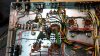
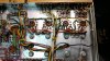
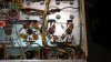
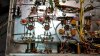
I removed the bottom cover today because I noticed the inrush current was immediate when turning on the unit. My Kill-a-Watt showed just over an amp at first power on then dropped to about 400 milliamps and slowly rose to about 900 mA during operation. I wanted to install a CL-80 at the least just to stop that initial current surge during warm up but I wasn't sure where I should install it. On the Scott I just put it inline with one of the AC wires going to the power switch but the Fisher's switch has a metal housing and insulator tube. It was just a precursory glance to familiarize myself with the unit. When I saw that someone had already hacked up one of the electrolytics and wired it a certain way, I guess my confidence took a little hit because now I was going to have to reverse engineer someone's repair. From what I can tell, looks like someone already went through and replaced the output coupling caps but there still may be some oldies that need replacing. What about that black and yellow one in the power supply question? And what do you suppose is underneath the black heatshrink on those two components connected to the electrolytics?

Just thought I'd get the opinions of those much more experienced than I so I can get some idea of direction to get this wonderful little amp in tip top shape. Thanks in advance for any comments or suggestions.

-Steve

IMG_20191108_054958425_HDR.jpg
IMG_20191108_055008788_HDR.jpg
IMG_20191108_055017950_HDR.jpg
IMG_20191108_055029895_HDR.jpg
IMG_20191108_055039563_HDR.jpg
 
Register to hide this ad
The Black cap (.01uf 600v) gets replaced with a standard .01uf 630V cap (Film cap is fine!). As for that Lytic on the side, if the red lead is tied to the + lead of C1 on the cap or via the terminal strip, without the cap being disconnected, you're treading on thin ice. It may be replacing C1 but is connected incorrectly! The components under the heatshrink is most likely DIODES SD1 & SD2. FISHER heatshrunk their Diodes from the advent of Solid State to about 1971.
 
Thanks Larry. So, can I assume the best course of action would be to return the electrolytics to their original configuration? Possibly with replacements from Hayseed Hamfest? That's what I did with the Scott and was happy to have shiny new cans and caps that will likely outlive me!

That red wire is going to the insulated pin for C1. Are these caps can positive like the Scotts? I'm not sure how to tell if the original cap has been disconnected.

And this is why I don't want to use the amp until I'm sure it's all wired and sorted properly.

-Steve
 
Also, the schematic says my output tubes should be 7189s but I've got OTK 6N14N-EBs? They're also marked IV84 which means...a version of EL84s?
 
The 6N14N-EB's are Russian Military equivalents of the 7189. They are fine for this application. It's a toss up between them, and the SOVTEK EL-84M as to which is better. Both very good and should last a long time. The IV84 is probably a date code. April of 84?????

With the Red wire to the body and the black to chassis ground, it's wired incorrectly anyway. Hayseed is one solution. And it gives you an "uncluttered, stock look" underneath.

Rebuild the power supply cap circuit with new lytics.
You can certainly add new diodes, but the old ones are probably ok. (if replaced use 1n4007's or UF4007's.)
Replace the C4 cap (use a .01uf 630V film cap) 505-M10.01/630/10 (Mouser #)
Replace the R64 2.2K 5W resistor with a 7W resistor. 72-RWM06222201JA15E1

If you want to install a CL-80,
1.) Remove the 2 wires (one AC Line and one to the switch) from the Terminal strip (MARKED IN YELLOW).
2.) Locate the 2 "unused" (verify this 1st) terminals (Marked in Blue) on the same terminal strip. Make sure neither is GROUNDED to CHASSIS!!!!
3.) If everything is good on the strip, the AC POWER wire and one leg of the CL-80 go to one terminal and the other leg of the CL-80 and the switch lead on the other terminal. No muss, No Fuss.
 
Wow, thanks Larry! When you say marked in yellow and blue, was there an attachment you meant to include? I didn't see any markings like that but I think I follow your instructions. That's a very elegant solution. Thanks for recommending that.

I really appreciate the Mouser P/Ns as well. From what I've read, it seems folks like to leave the Erofols? I've only got a couple on the phono and tape preamp tubes, the .022uF. I assume there were others but looks like someone replaced them with ceracaps at some point. Oh, and looks like there's an Erofol on the tone controls too, labeled .0033uF. The schematic calls out .033uF. Typo?

I'm going to install the CL-80 this morning. If I wanted to wire in that 100uF electrolytic the correct way until I get HH replacements, Do I just need to move the black wire over to a negative lead on C2? Or do I also need to change the red wire hookup? If I'm understanding correctly, the main reason it's incorrect right now is because we don't know if the original has been taken out of the circuit? It doesn't appear to be. Instead it looks like whoever added that 100uF replacement merely used the old C1 positive terminal as a connecting point. And holy cow, what an ugly solder joint that one is!

I'm in the middle of rebuilding some late 70's Speakerlabs right now and just wanted to give the Fisher a quick once over until the speaker components show up so my goal is to get the CL-80 in and keep the Fisher usable until I can get the new caps and resistors. But if I can get C1 correctly wired up as well that would be a bonus. Unless you think I should hold off and do it all in one operation so I can get bias and all other adjustments made at the same time. Bias and balance questions to come :)

Thanks again sir!

-Steve
 
After making an embarrassing mistake by only using one of the terminals for my connections (thank you John, aka nerdorama) I got the CL-80 installed:
IMG_20191109_100819637.jpg
Current is no longer jumping to over an amp, but instead is about 500mA when first turning on the unit. Then it drops to about 300mA and slowly climbs to it's normal operating current of about 850. Thanks for all your help Larry! If you have time, could you guide me on how to properly connect up that 100uF electrolytic? Unless you don't think it's not worth messing with until I'm ready to replace it with Hayseed Hamfest? Speaking of which, they had many sets of power supply caps for sale but none of them had all of the correct values for my X-100-2. Tom at HH said they could make whatever I need so it looks like I may have to take him up on that offer. Is it true that the X-100-2 is that rare? Not in the sense that it's more valuable but just that Fisher was just trying to clear out parts and made different model variations in order to do that?

-Steve
 
Last edited:
Sorry about that. Here's the pic marked up.
X100-2 PS.jpg

The X-100-2/X-100-A was one of the last of the FISHER TUBE Integrated's. By then Solid State was taking over and manufacturers had either transistioned over totally or were in the process. FISHER tended to drag it's feet.

Take the spec's for the CANs right out of the Service Manual. Don't forget to indicate the marker shapes. I've been using Hayseed for better than 10 years now, and not one failure or bad one in the bunch. As he gets orders for new models, He'll add that model to the list.
 
Hey guys,

Not saying that I won't take up the challenge of going through my X-100-2 but before I post a detailed thread about my amp, I was wondering if there were any Fisher experts in the Seattle/Tacoma area? I'm relatively new to tube amps but learned a lot recapping, modifying and adjusting bias on my Scott LK72 a few weeks ago. I would like to try and do the same for the Fisher but I'm finding that the X-100-2, at least, doesn't quite have the documentation available. Nor does it have the number of threads and info about others who have worked on them.

It looks like you are doing good work on your Fisher... If you would like an experienced person to look at them, forum member @blhagstrom lives in the area and recently did a very nice job of restoration on a pair of Fisher 70A amps for me... You may want to contact him.
 
Great to know! Thanks for the recommendation. If I get stuck I'll get in touch with him. Or, I may just reach out to him anyway. You never know if he may have other gear he needs me to buy ;)

-Steve
 
Back
Top Bottom