• The move to the new server is done. There are some software and database maintenance updates in process. This has us passing the hat around to help out. We appreciate any donations. Seriously, even a dollar helps. The payment page may be found here - https://www.audiokarma.org/support.html

AR-XA tonearm ground wire?

jleon92f

Addicted Member
Good Morning,

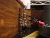
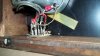
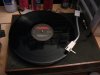
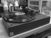
On the AR-XA tonearm there is a braided wire attached to the pivot of the arm.
When you upgrade the headshell to a bayonet mod, the extra ground on the end of the tone is attached too under the base where the RCA cables are. :scratch2:

Thanks for any replies.:thmbsp:
John :music::D
 

Attachments

  • PICT0121.jpg
    PICT0121.jpg
    50.7 KB · Views: 206
  • 036.jpg
    036.jpg
    72.2 KB · Views: 195
  • 037.jpg
    037.jpg
    72.3 KB · Views: 170
  • IMG_3587-L.jpg
    IMG_3587-L.jpg
    142.5 KB · Views: 203
Register to hide this ad
Good Morning,

On the AR-XA tonearm there is a braided wire attached to the pivot of the arm.
When you upgrade the headshell to a bayonet mod, the extra ground on the end of the tone is attached too under the base where the RCA cables are. :scratch2:

Thanks for any replies.:thmbsp:
John :music::D
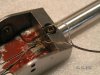
Hi John, if you're keeping original RCA cables, the grounds get summed at the preamp via the ground running down one RCA to the male connector.

However, I now sum all grounds at the buss strip. right cart, left cart, arm/chassis ground. This produces a much quieter background by having every possible ground being on the same potential.
 
Marc - first time poster here from the UK. Your reply has encouraged me to join.

I have an XA with a replacement arm tube /headshell into the stock pivot and using the original RCA lead. The arm is rewired but I believe I am using the standard configuration.

I have a mild buzz if I turn volume to max. It is not an issue for normal listening but does prevent me from using the deck for PC transfers where I want as clean a transfer as possible.

You appear to be describing an alternative configuration but I don't understand what you mean by "I now sum all grounds at the buss strip. right cart, left cart, arm/chassis ground". Is this a different configuration using the stock RCA lead or does it require a replacement lead?

I don't recall seeing you describe this in detail in any other posts so more information would be helpful to me.

Thanks
 
Hi John, if you're keeping original RCA cables, the grounds get summed at the preamp via the ground running down one RCA to the male connector.

However, I now sum all grounds at the buss strip. right cart, left cart, arm/chassis ground. This produces a much quieter background by having every possible ground being on the same potential.

Hi Marc, 1st off thanks for your reply. I replaced the original RCA cables with New one's from KAB and the ground wire also. I believe it is the arm/chassis ground I am interested in connecting. It screws to the back of the pivot housing and it was connected on the Buss strip Left channel.

The background is quiet but, their is some noise when touching the tonearm.

Thanks again.
John.:D
 

Attachments

  • 045.jpg
    045.jpg
    52.1 KB · Views: 148
  • 031.jpg
    031.jpg
    35.8 KB · Views: 121
Marc - first time poster here from the UK. Your reply has encouraged me to join.

I have an XA with a replacement arm tube /headshell into the stock pivot and using the original RCA lead. The arm is rewired but I believe I am using the standard configuration.

I have a mild buzz if I turn volume to max. It is not an issue for normal listening but does prevent me from using the deck for PC transfers where I want as clean a transfer as possible.

You appear to be describing an alternative configuration but I don't understand what you mean by "I now sum all grounds at the buss strip. right cart, left cart, arm/chassis ground". Is this a different configuration using the stock RCA lead or does it require a replacement lead?

I don't recall seeing you describe this in detail in any other posts so more information would be helpful to me.

Thanks

run a jumper from both cart grounds to the arm/chassis ground at the buss strip. That will sum all the grounds to the same potential from the buss to the preamp.

also check ground from your pivot block to arm tube. Sometimes the screw that holds the tube make for a poor ground.

you also might be experiencing the difference in AR wire pattern and "SME"
AR is red right hot, black right gnd. Green is left gnd on AR. if you sum, it won't make any difference.
 
run a jumper from both cart grounds to the arm/chassis ground at the buss strip. That will sum all the grounds to the same potential from the buss to the preamp.

also check ground from your pivot block to arm tube. Sometimes the screw that holds the tube make for a poor ground.

you also might be experiencing the difference in AR wire pattern and "SME"
AR is red right hot, black right gnd. Green is left gnd on AR. if you sum, it won't make any difference.

Thank you very much..:thmbsp::D
This is what was there before..:scratch2:
John.:music::D
 

Attachments

  • 016.jpg
    016.jpg
    68.4 KB · Views: 143
I have to redo the preamp ground location too..:scratch2: It is not connected to the Buss..:D

Sounds great though, Nice and smooth all the way to the end. Vocals clean and clear. I was worried about the overhang. :scratch2:

Thanks,

John.:music::D
 

Attachments

  • 021.jpg
    021.jpg
    48.9 KB · Views: 103
  • 040.jpg
    040.jpg
    56.7 KB · Views: 100
  • 039.jpg
    039.jpg
    81.5 KB · Views: 105
Marc - thank you for your reply. It was late here when you posted so I have had a look this morning.

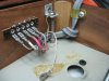
If we take the 4th of the photos that John has helpfully posted this shows the RCA lead connected to what I believe you are referring to as the buss. This photo does not show the wires from the tone arm which need to be connected/soldered in the correct order to correspond to equivalent connectors on the RCA lead.

Looking at the sequence on the photo from left to right if my understanding is valid this would be blue tonearm wire to silver, white wire to white, red wire to red, green wire to bronze and ground (braided wire or equivalent) to grey. Like John I have one wire from the grey connected to the plinth screw and the other which he shows as loose is connected to my top plate.

If I understand what you are suggesting then I need to manufacture a link between the silver and bronze ground wires or between blue and green. I assume either would work.

I have looked at the screw into the arm block on several occasions trying alternative screws and even replacing the braided wire so unless there is an inherent problem I don't believe the issue is there.

I am not currently using a bayonet headshell but have a "straight arm fixed headshell" arrangement with cardas wires direct from the cartridge tags through to the "buss". I previously had the same buzzing when I tried an s bend arm tube and sme type bayonet headshell. No difference with alternate cartridges.

John - I don't wish to divert the thread off topic from your own questions but think my issues are relevant to your concerns about configuration. I am interested in possible alternate configurations including what you are doing. Let me know if you would prefer I go offline with Marc.
 
Last edited:
Marc - thank you for your reply. It was late here when you posted so I have had a look this morning.

If we take the 4th of the photos that John has helpfully posted this shows the RCA lead connected to what I believe you are referring to as the buss. This photo does not show the wires from the tone arm which need to be connected/soldered in the correct order to correspond to equivalent connectors on the RCA lead.

Looking at the sequence on the photo from left to right if my understanding is valid this would be blue tonearm wire to silver, white wire to white, red wire to red, green wire to bronze and ground (braided wire or equivalent) to grey. Like John I have one wire from the grey connected to the plinth screw and the other which he shows as loose is connected to my top plate.

If I understand what you are suggesting then I need to manufacture a link between the silver and bronze ground wires or between blue and green. I assume either would work.

I have looked at the screw into the arm block on several occasions trying alternative screws and even replacing the braided wire so unless there is an inherent problem I don't believe the issue is there.

I am not currently using a bayonet headshell but have a "straight arm fixed headshell" arrangement with cardas wires direct from the cartridge tags through to the "buss". I previously had the same buzzing when I tried an s bend arm tube and sme type bayonet headshell. No difference with alternate cartridges.

John - I don't wish to divert the thread off topic from your own questions but think my issues are relevant to your concerns about configuration. I am interested in possible alternate configurations including what you are doing. Let me know if you would prefer I go offline with Marc.

If your running an alternative arm, then the cart arm wires should follow "SME" Red/Green and White/Blue. If you've removed the mesh ground screen and replaced it with a single wire, that's OK. But you want to twist the cart wires where they exit the block, red/geen one direction, white blue the other direction, and then braid those twisted pairs with the ground wire. That will provide shielding for high freq emi (radio, etc) low freq EMI (50-60hz) can't be shielded, and isn't shielded anyway. which buss strip pins you attach the wires to is up to you, but originally they were (top to bottom)
left gnd, left hot, rt hot, rt gnd, chassis gnd. simply attach the RCA H/G wires to the correct arm H/G. run a jumper across the cart grounds at the buss and attach that ground to the chassis ground. you do not then need to run a separate ground wire from the table to the preamp, as the RCA cable grounds are doing that job. This way gives you only 1 ground potential.
 
I have to redo the preamp ground location too..:scratch2: It is not connected to the Buss..:D

Sounds great though, Nice and smooth all the way to the end. Vocals clean and clear. I was worried about the overhang. :scratch2:

Thanks,

John.:music::D

summing all the grounds at the buss eliminates the need for a separate ground wire.

original offset at stylus in the AR arm when set to AR specs was 23deg at 15mm overhang. setting the overhang to 16.5mm will cut tracking error distortion by 50% and put the inner null into the last cut instead of the run out groove. A slotted headshell will allow you to set it to baerwald by putting a slight twist in the cart to increase offset angle slightly.

getting a crackle or static sound when touching the tube is a poor ground connection between the tube and pivot block. The threads that hold the bolt can be crappy, the bolt surface can be crappy, the surface of the armtube can be crappy...and all of the above.
 
Marc - thanks

The cardas wire I am using is already braided along its length through the arm tube and stock pivot apart from either end where I have unravelled in order to solder direct to the cartridge tags and to the buss. I have not tried to braid the alternative ground wire to the cardas but I will eventually give that a go. I don't think I am having any interference but no harm in playing safe. I did not want to braid the ground until I am sure which wire to stick with.

On my deck I am using the order you describe for the sequence of wires. John is using a slightly different order in his photo. As you say that should not matter provided the arm wires are configured in line.

I will try to construct a suitable jumper across the grounds this evening.
 
Bit of a frustrating day. In trying to bridge the two grounds I managed to dislodge one of the previously soldered wires. As a result I rediscovered what real hum sounds like (several times) first in the right channel then in the left where my lack of soldering skills were exposed. Now got it back to where I was but need to be a bit cleverer with the bridging. Not sure if my efforts so far have been good enough. My local electronics shop did not really have anything I could use so I am trying to identify if I have got anything around the house that will do the job properly.

I did have another look at the screw at the base of the tonearm. Tried retightening it after spraying the general area with contact cleaner. I am thinking about soldering the ground wire to the inside of the arm tube to avoid the use of the base screw entirely.
 
Managed to finally bridge left ground to right ground to tonearm ground. Unfortunately the buzzing is still there. Looks like I will need to do more work with the screw at the base of the tonearm to verify if the problem lies there.
 
Managed to finally bridge left ground to right ground to tonearm ground. Unfortunately the buzzing is still there. Looks like I will need to do more work with the screw at the base of the tonearm to verify if the problem lies there.

you need to get an ohm meter to check where there is a possible poor or open ground.
 
Marc - thanks - just got a new digital multimeter out of its packaging. Unfortunately I am somewhat ignorant of what to do next. I assume I need to check between various points from the tonearm base screw through to the end of the RCA plugs at the amplifier end. What am I looking for?
 
So the separate ground I have connected to the 'T' bar is not needed? :scratch2: I am getting a new hum? :scratch2:

John.:music::D


summing all the grounds at the buss eliminates the need for a separate ground wire.

So the separate ground I have connected to the 'T' bar is not needed? :scratch2: I am getting a new hum? :scratch2:

John.:music::D


original offset at stylus in the AR arm when set to AR specs was 23deg at 15mm overhang. setting the overhang to 16.5mm will cut tracking error distortion by 50% and put the inner null into the last cut instead of the run out groove. A slotted headshell will allow you to set it to baerwald by putting a slight twist in the cart to increase offset angle slightly.

getting a crackle or static sound when touching the tube is a poor ground connection between the tube and pivot block. The threads that hold the bolt can be crappy, the bolt surface can be crappy, the surface of the armtube can be crappy...and all of the above.
 
So the separate ground I have connected to the 'T' bar is not needed? :scratch2: I am getting a new hum? :scratch2:

John.:music::D

Are you running the subchassis ground separate from all the rest of the grounds? if so, you need to get that summed to the arm ground and RCA grounds.
 
Completed..:thmbsp:
 

Attachments

  • M91ED_2015.jpg
    M91ED_2015.jpg
    35.2 KB · Views: 66
  • ar_xa_almost done.jpg
    ar_xa_almost done.jpg
    72.7 KB · Views: 62
  • new stylus m91ed.jpg
    new stylus m91ed.jpg
    56.2 KB · Views: 54
  • VTF_m91ed.jpg
    VTF_m91ed.jpg
    30.4 KB · Views: 66
Pleased to see that John is now sorted.

Unfortunately I am still floundering. I think I had lessons on electrical circuits when I was at school but that was probably around the time the deck was manufactured and clearly the lessons did not sink in because I don't really know what is ok or what is not.

I located what appears to be useful guidance for general checking on this thread at VE. See the post by Joe Z.

http://www.vinylengine.com/turntable_forum/viewtopic.php?t=28698

Using this I have done continuity testing at various locations. I think I am ok with connectivity from cartridge tags through to the soldered ends on the buss strip including the ground connection from the base of the tonearm.

I have noticed something with the RCA spade connectors to the buss. The spade for the silver coloured left ground has continuity to the spade connector for the main ground. I believe this is ok. However when I press this spade connector onto the buss strip I have noticed that if I then check for continuity between the white left channel and the main ground then the meter starts to react moving away from 1. It does not result in a beep from the meter so it is not full continuity. Is this behaviour normal or indication of an issue?
 
Back
Top Bottom