• The move to the new server is done. There are some software and database maintenance updates in process. This has us passing the hat around to help out. We appreciate any donations. Seriously, even a dollar helps. The payment page may be found here - https://www.audiokarma.org/support.html

ARC SP-11 owners -- a little help?

Jfaustus

AK Subscriber
Subscriber
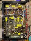
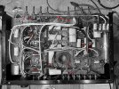
I committed the cardinal sin: I bought a 'for repair' unit without looking under the hood. I KNOW. Fortunately I didn't pay much at all. Unfortunately, the unit is a 100%, 11 out of 10, bona fide basket case.

But it's an SP-11 so I am going to give it the old college try. The repair is above my pay grade but that's how I prefer to learn.

There are more issues than you can shake a stick at, like what the heck is that breadboard doing stuck to the side?!?

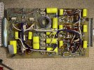
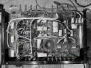
Right now what I'm hoping to address is a big part of the smaller top board over the pots is broken off. Just... snapped. So the first order of business is to get a new board made. To to that I need pics of an unbroken example. Nice crisp images of the top of the board are readily available on the web. What I would LOVE some help with (and thank you in advance) is getting some good images of the bottom. There's plenty of room there so I hope it won't be too too much trouble for someone to stick their phone on closeup mode and snap a couple of pics.
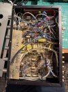
IMG_4083.jpegIMG_4084.jpeg
 
Last edited:
Register to hide this ad
What a mess! Who would do/let that happen to such a nice piece of high-end gear?? I hope the power supply is in better shape.

I wish you luck. You have quite the task ahead. I've recently developed a lusting for a SP-9 but found out it will not fit in my rack.
 
What a mess! Who would do/let that happen to such a nice piece of high-end gear?? I hope the power supply is in better shape.

I wish you luck. You have quite the task ahead. I've recently developed a lusting for a SP-9 but found out it will not fit in my rack.

Yes it will be a long labor. I will certainly learn a lot. With some luck, I will end up with a unit I could never buy in working condition. And honestly? Even if I fail I know I’ll enjoy the ride.
 
I hope the power supply is in better shape.
LOL. Tue power supply is why I thought I was buying cheap. It’s missing altogether. I have a plan for that though, and most of the parts. Each of these will have their own thread once I get into them.
 
Although I have never looked closely, I've seen people questioning about replacing/substituting the power supply for the SP11. I seem to recall the main issue is not know what the output voltages are suppose to be. Getting that figured out very well may be the easiest part of your journey.

Looking forward to seeing how this all comes out.
 
Although I have never looked closely, I've seen people questioning about replacing/substituting the power supply for the SP11. I seem to recall the main issue is not know what the output voltages are suppose to be. Getting that figured out very well may be the easiest part of your journey.

Looking forward to seeing how this all comes out.
Thanks! I do have some advantages, especially on the PS. One is that I do have the umbilical. That's a big plus. And I've zeroed in on the par numbers for the pins etc for the receptacle on the PS side. It seems the HV part of the PS was run at the edge and sometimes went boom. Could be why this one is missing. Folks at diyaudio recommendd upgrading with Jan Didden's HV circuit so that's what I'll do.

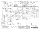
The schematic seems pretty clear about needed voltages but maybe I'm missing something?

Screenshot 2026-04-20 at 9.46.50 AM.png
 
Functionally speaking, what does that board do besides making connection between the pots and the wiring? If it doesn't do anything else, wire landed right on the pots is fine. I'd do a better job than the last person did though. Also I wouldn't be using salvaged wire out of motors. Those leads with numbers? Those look like the connection leads for a 3 phase motor. Its not bad wire, just a fair bit fatter than it needs to be.

Further guess here, someone may have replaced the pots and instead of getting PCB pin type they got solder eye and decided to chop the board to make them go. Looks like it was gone at with a pair of side cutters. The right way would have been to get the correct pots, or make short jumpers to tie them to the board. A less ugly way would have been to cut the board straight with a saw.
 
Functionally speaking, what does that board do besides making connection between the pots and the wiring? If it doesn't do anything else, wire landed right on the pots is fine. I'd do a better job than the last person did though. Also I wouldn't be using salvaged wire out of motors. Those leads with numbers? Those look like the connection leads for a 3 phase motor. Its not bad wire, just a fair bit fatter than it needs to be.

Further guess here, someone may have replaced the pots and instead of getting PCB pin type they got solder eye and decided to chop the board to make them go. Looks like it was gone at with a pair of side cutters. The right way would have been to get the correct pots, or make short jumpers to tie them to the board. A less ugly way would have been to cut the board straight with a saw.
I had the same thought re the replacement pots. And I’m sure you’re right about the wiring. The board is the nice and elegant way to do it. And if I can be sure of the layout it won’t cost much to remake. But direct wiring will be my fallback. In any case I’ll have to strip out everything the hack artist did…
 
What a mess! Who would do/let that happen to such a nice piece of high-end gear?? I hope the power supply is in better shape.

I wish you luck. You have quite the task ahead. I've recently developed a lusting for a SP-9 but found out it will not fit in my rack.
I used to wonder this myself. A very common abuse of high-end gear is that the owner dies and the (incomplete) piece is sold for $25 at the estate sale and then thrown into the buyer's van with the other loot later to be sold on ebay.
There are more issues than you can shake a stick at, like what the heck is that breadboard doing stuck to the side?!?

Right now what I'm hoping to address is a big part of the smaller top board over the pots is broken off. Just... snapped. So the first order of business is to get a new board made. To to that I need pics of an unbroken example. Nice crisp images of the top of the board are readily available on the web. What I would LOVE some help with (and thank you in advance) is getting some good images of the bottom. There's plenty of room there so I hope it won't be too too much trouble for someone to stick their phone on closeup mode and snap a couple of pics.
Geez, you have a lot of work ahead of you! IMO, it looks like this SP-11 was owned by an engineer who just wanted a working preamp. The breadboard on the side is probably a couple of opamp gain or buffer stages. I don't think the owner had a SP11PS, based on what this work looks like. I suspect some of the FETs in the line stage went bad and rather than replacing them, an opamp linestage was built.

If you want your pre to be an SP11, I recommend disconnecting all wires to/from the breadboard and pots - take the whole thing out and see what you have left to work with. Some ARC matched FETs are available from a member on another audio forum.

Otherwise, this could be a curbsider - depends on your goal and determination.

I am presently rescuing an SP11 and will be happy to share some of what I have generated ahead of the web page that I intend to post on completion.

*NB This information is not complete.


-JamesW-
woodman1200.com
 

Attachments

  • SP11_bottom1.jpg
    SP11_bottom1.jpg
    242.2 KB · Views: 2
  • SP11_bottom2.jpg
    SP11_bottom2.jpg
    250.3 KB · Views: 2
  • SP11_bottom_wire_map.jpg
    SP11_bottom_wire_map.jpg
    222.6 KB · Views: 2
  • SP11_PS_connection_map.jpg
    SP11_PS_connection_map.jpg
    222.8 KB · Views: 2
Back
Top Bottom