• The move to the new server is done. There are some software and database maintenance updates in process. This has us passing the hat around to help out. We appreciate any donations. Seriously, even a dollar helps. The payment page may be found here - https://www.audiokarma.org/support.html

ARC SP-14 stopped turning on (did I fry my preamp?)

goldencalves

New Member
Hi y'all, long-time forum lurker, first time poster.

I very recently came into possession of an Audio Research SP14, in very good shape from a very reputable dealer (online, but with a high end brick and mortar store). Worked perfectly fine, sounded great on CD, but realized the phono out sounded very off (overly bassy, mids and highs dramatically muffled).

During a test I plugged it in, switched it on, and it immediate smoked; I flipped it back off after being turned on for maybe 5-10 seconds. Has not turned on since. Cannot find a clear source of the smoke and burnt/ozone smell.

The details: I had been pouring over the manual (link here) anyways because of a resistor that had visibly blown, and figured out that in the ARCs the cartridge impedance was controlled by resistors soldiered to the phono stage and that an obscure impedance had been installed (237 ohms I think?!?), and I needed to get it back to the factory set 47k.
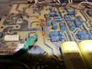
IMG_5235.jpeg
(the impedance resistors for the phono cart stage, soldiered to these posts, connected to C36 (560 pfd cap).

The Manual/schematic has no listing of any 47k ohm resistors anywhere. I scoured the internet trying to find any images of the board (plenty of ok photos of the top, basically none of the underside of the board). I finally picked a grainy still from a 10 year old video on YouTube that appears to show no factory standard impedance resistors in place of where the 237ohms(?) were on mine. Inferred that possibly the 47k resistance was somewhere else in the circuit (somehow).

In an impulsive decision right before lunch (I blame low blood sugar), to see if removing the 237(?) ohm resistors made a difference, plugged it in and it blew.

2 other absurd mistakes that I made concurrently:

  • I forgot to reinstall the phonostage 6DJ8 tube (V1)
  • I mixed up some cables and plugged my old phono amp outputs into the ARC main output (the old phono amp (an ifi phono) was on but had no inputs connected, only outs to the ARC)

Are there capacitors or circuits I should focus on specifically? Any readings I should look for? Did I potentially fry my main power?
I've been pouring over the amp, the manual, the internet. I'm a moderate novice (have built a bottlehead amp from kit, have performed very modest repairs on electronics), and just cannot find a path to figuring out what to look for and how to even interpret the readings from the Arc, and really have no idea which of these 3 mistakes I had made even created the power failure (maybe a combo of 2 or 3?).

I scoured the board and didn’t see any burnt spots outside of what (probably) existed when it was working:

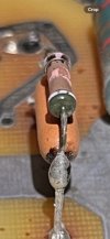
  • This resistor with a burnt resistor jumped on top 46A. The yellow orange unmarked longer resistor was what I think was standard, but has no markings. I believe that the smaller resistor on top was jumped to make up for the diminished resistance of the yellow orange.
  • IMG_5181.jpeg
  • IMG_5203.jpeg

  • This capacitor C21 (1500uf 35v) that looks bad (bulgy at the top, some sort of burn/rust spots). I clocked this after the power issue but I think it probably came bad like this
IMG_5244.jpeg
(the 50 OHM 1% resistor (46) is connected in parallel to the 46 resistor on the other side of the board).
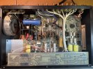
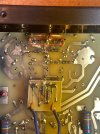
IMG_5237.jpegIMG_5236.jpeg
(Bottom and tops of the boards)

I've already ordered replacements for the affected resistors and caps that I know should be replaced, and I'm guessing there will be at least a few more.
Anyways I am pretty gutted by this, this was a huge upgrade for me (from a $120 adcom preamp). Its really a beauty, sounded amazing while I could listen. I'm hoping its salvageable, and am guessing it will take some hours.

Thank you if you've taken the time to read through this and extra thanks in advance if you respond.

Cheers,
Chris
 
Register to hide this ad
nicely written first post, welcome to the other aspect of an online forum... interaction.

large, easy to read photos always a plus. good choice, thank you for that.

tube preamp should be relatively easy for troubleshooting since it has fewer components vs solid state equivalent, usually. testing the health of each tube/bottle/bulb/glassware would be a good start. the b+ on this system should be lower than the typical tube amp but i need to look around for schematics and general design research.

*possibly a redundant link vs the first post content.

looks like the schematic starts on page 16 of the manual. more solid state in here than expected, this could be a problem. some things just dont age very well and if its close to an extreme heat source all bets are off. best bet would be to verify most of the resistor&cap values with a dmm or LCR meter since a component can look shiny and new but measure open or shorted. aged caps will have a higher esr value (cap turning into a resistor syndrome). once the cap starts to have a resistance more than a capacitance it creates a destructive path for real high voltage (b+, b1, b2) which yields a kaboom or burn/fire.

*small pieces of info, not sure if this is of immediate value.

need to study the schematic more before i can attempt to type something useful. my experience with tube gear is nowhere near the 30-40 years like most in the audio valve community but i have had a few systems go across the bench in the right direction, happy owners.
 
Thank you so much for your response.

[/URL] *small pieces of info, not sure if this is of immediate value.

I've bookmarked the AK ARC preamp thread, will read over it this evening (any insight into how these are put together and function is helpful for trying to figure out what to look for is really helpful, I've picked up bits and bobs in other threads that have helped wrap my brain somewhat around whats going on in the box).

best bet would be to verify most of the resistor&cap values with a dmm or LCR meter since a component can look shiny and new but measure open or shorted. aged caps will have a higher esr value (cap turning into a resistor syndrome). once the cap starts to have a resistance more than a capacitance it creates a destructive path for real high voltage (b+, b1, b2) which yields a kaboom or burn/fire.

I did just order a new multimeter yesterday to upgrade my bargain model that cannot read capacitance, but the upgrade is not explicitly an LCR (its a Triplett 9045, recommended in another AK thread for this purpose; is there a better/more efficient option than this?).

Given the areas for potential shorts, would it be worth it to just focus on testing all of the resistors/caps in the phono and power circuits, or would it just be worth it to go over the whole board? Investing in a de-soldering iron pump and fume extractor right now regardless (for the record, I usually don't buy so much from Amazon, trying to get most everything I can from digikey or elsewhere).

Thanks again,
Chris
 
any insight into how these are put together and function
after looking through the schematic it would appear this preamp has one tube (phono section) and everything else is solid state (fet's galore with arc part numbers and color codes).

to get the party started it would be best to establish what your familiarity of basic electronics is? an example would be component recognition and function of each e.g. a resistor restricts flow of power/electrons/current/amperage vs a capacitor that passes ac and blocks dc. learning the ins and outs of field effect transistors (fet) can be useful although try not to fall into the rabbit whole of component/circuit theory it gets deep fast.

something to be mindful of is sensory overload. looking at an unfamiliar piece of electronics can seem overwhelming, breaking it down into small pieces can help. focusing on power supply circuit for any shorted components and diode check silicon devices (diodes, transistors, fet's).

a simple circuit simulator can help with visualizing what is normally invisible to humans.

*a relatively easy to learn interface and nothing to install on a computer, also various circuit examples. options > conventional current motion (deselect for electron flow version)

other options exist like:

and a few others depending on personal learning curve and gui preference.

*nice start except is seems expensive for such a limited screen, critiquing from personal preference (everybody is different).

*a recent acquisition i am getting comfortable with but some of us also have terrible eyesight among an assortment of health issues.

an LCR meter is a good investment for a more specialized evaluation of components even though testing in-circuit has some limitations. case in point, a 100r resistor in parallel with an inductor. the inductor will cause the resistor to measure as a dead short even though the resistor will be fine (measure outside of circuit required).

*i am using a de-5000 and it seems to be decent with a few flaws


there are obviously better meters out in the world but finding something new/newer and at a reasonable price is a challenge. transistor checker also useful.


now back to the preamp and testing methodology. all electrolytics should be replaced due to age, aka the recap of old/vintage gear. in this case there is most likely a root cause of initial failure like a dried up cap that allowed too much dc leakage to occur and then kaboom somewhere (weakest link exploited).

measuring components in the initial area of concern, phono section, is a good start but who knows what else upstream in the circuit has an issue or is damaged. passive testing at this point i.e. no power applied until a sanity check of the major players/components is accomplished.
 
Thank you once again for the thorough and helpful response.
to get the party started it would be best to establish what your familiarity of basic electronics is? an example would be component recognition and function of each e.g. a resistor restricts flow of power/electrons/current/amperage vs a capacitor that passes ac and blocks dc.
I am around a level 2 novice. I can recognize most of the electrical components and their most basic functions but not how it all fits together and interacts in a comprehensive way.

a simple circuit simulator can help with visualizing what is normally invisible to humans.

https://www.falstad.com/circuit/circuitjs.html *a relatively easy to learn interface and nothing to install on a computer, also various circuit examples. options > conventional current motion (deselect for electron flow version)

other options exist like:
I did not know that sites like this existed, and they are pretty amazing. I’ve begun a couple of electrical/electronics text books in the past and have been meaning to revisit them, but that falstad simulator is very effective at communicating several ideas I’ve struggled to grasp from text alone.

I’m starting to go through the intro videos for the circuitlab right now.

https://www.amazon.com/s?k=owon+xdm1241 *a recent acquisition i am getting comfortable with but some of us also have terrible eyesight among an assortment of health issues.

an LCR meter is a good investment for a more specialized evaluation of components even though testing in-circuit has some limitations. case in point, a 100r resistor in parallel with an inductor. the inductor will cause the resistor to measure as a dead short even though the resistor will be fine (measure outside of circuit required).

https://www.amazon.com/s?k=lcr+meter *i am using a de-5000 and it seems to be decent with a few flaws

https://www.deree.com.tw/de-5000-lcr-meter.html

OK I took a look at all these, compared them to that Triplett multi, and took your advice, splurged on the OWON and de-5000 and will return the Triplett. These all look like they’ll be a lot easier and efficient to work with.

all electrolytics should be replaced due to age, aka the recap of old/vintage gear. in this case there is most likely a root cause of initial failure like a dried up cap that allowed too much dc leakage to occur and then kaboom somewhere (weakest link exploited).

measuring components in the initial area of concern, phono section, is a good start but who knows what else upstream in the circuit has an issue or is damaged. passive testing at this point i.e. no power applied until a sanity check of the major players/components is accomplished.

Am waiting on a few parts and pieces from Digikey that I know will have to go in (that cap and those handful of resistors); once those are installed will embark on the process of going piece by piece throughout the rest of the board. Will report back any findings/dead ends.

Thanks again, this has all been extraordinarily helpful input and suggestions.
 
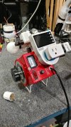
another item to add to the acquire/construct list would be a modified dim bulb fixture. using a filament high wattage bulb to limit circuit current when applying power for the first time after the first batch of repairs are installed. several threads and examples on audiokarma. i did an update about my variac hybrid dim bulb setup a few pages ago in the diy>menagerie thread.

dim -12.jpg
one of the photos used in the thread
 
Back
Top Bottom