• The move to the new server is done. There are some software and database maintenance updates in process. This has us passing the hat around to help out. We appreciate any donations. Seriously, even a dollar helps. The payment page may be found here - https://www.audiokarma.org/support.html

Attempting to fix my dads RFT k13ProfiL

waxdaddy

New Member
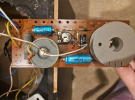
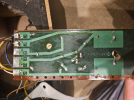
Trying to fix this speaker. Both drivers are working (tested them by holding the audio cable from my receiver directly to the contacts on the drivers) so i think there is a short on the pcb board. I know very little about electronics so it's hard for me to follow the path of current. I tried testing all the components using a continuity meter and most of them seem to be fine. Theres a bunch of them in the middle with the frolyt 100/25, the two 4 striped resistors and the brown one next to where it says VD1 that do not produce the sound.

Im sure i didnt do a very good job explaining so please ask questions to clarify! I just dont know enough about electronics to be any more coherent.

Adding pictures of the pcb and a circuit diagram found online
 

Attachments

  • Screenshot 2024-02-04 084417.png
    Screenshot 2024-02-04 084417.png
    994 KB · Views: 16
  • Screenshot 2024-02-04 084432.png
    Screenshot 2024-02-04 084432.png
    962.5 KB · Views: 16
  • Screenshot 2024-02-04 150042.png
    Screenshot 2024-02-04 150042.png
    7.4 KB · Views: 15
Register to hide this ad
It's unlikely to be a short. Testing each driver was a good first step. The two blue and one black components are electrolytic capacitors, and at this age they're probably due for replacement. However...that wouldn't explain not getting any sound from the woofer (I'm assuming you're not getting any sound whatsoever when they're in the cabinet). If that's the case, I'd check to make sure there is continuity from the input terminals (test on the side where you actually connect the speaker cables from your amp) to the PCB. Looking at the schematic, the input terminals and wires are the only things that the woofer and tweeter share. If that checks out OK, we'll have to assume that there are at least two failures. Use the resistance setting on your meter and measure between the input wires and the woofer wires. One should read 0Ω, the other should read the same or slightly higher than that (due to the inductor which has a small amount of resistance). If one or both gives you no reading, that probably means a bad connection on the PCB.
 
My bad I was not detailed enough. The woofer gets sound when everything is put together. Only the tweeter is out. Should I still follow the same series of tests?

Edit: I tested the resistance from the input terminals to the output terminals:
E+/T+ 0
E+/T- 0.006
E+/H- 0.006
E+/H+ 0.011

E-/T+ 0.005
E-/T- 0
E-/H- 0
E-/H+ 0.004
 
Last edited:
You may have bad capacitors - the cylindrical blue things. They appear to me to be electrolytics, which age and can go bad. Replace them either with new electrolytics or with film caps (though film caps may make the speaker brighter).
The other possibility is that the pots on the board need clearing. Take pictures of each board, use a small screw driver to turn the pots back and forth, and then return them to the exact orientation they were, and see if that solves the problem.
 
Is there a way to test if the capacitors are bad without replacing? I don't mind doing it but since I'm a beginner at soldering it would take me a long time. (Also would prefer to only replace the ones that are indeed aged out)

Also which parts are the pots?

By the way I forgot to mention that these speakers were working perfectly until I sent them from europe to the US. I believe I packaged them badly or TSA messed them up when they opened the box. Just wanted to mention this in case it affects your train of thought.
 
Is there a way to test if the capacitors are bad without replacing? I don't mind doing it but since I'm a beginner at soldering it would take me a long time. (Also would prefer to only replace the ones that are indeed aged out)
You'd have to remove one leg from the board for each cap to test it properly. Also, you'll need a meter that has a capacitance tester (most standard DMMs don't).
Also which parts are the pots?
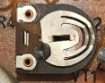
There's only one pot (short for potentiometer). That's the component in the center of the board, the D shaped brown and silver thing with the rectangular slot (meant for a screwdriver so you can turn it). These can become oxidized with age, and turning it back and forth will remove enough oxidation so some signal can get through, at least temporarily.

ETA: this is the pot:

1707099466030.png
 
You'd have to remove one leg from the board for each cap to test it properly. Also, you'll need a meter that has a capacitance tester (most standard DMMs don't).

There's only one pot (short for potentiometer). That's the component in the center of the board, the D shaped brown and silver thing with the rectangular slot (meant for a screwdriver so you can turn it). These can become oxidized with age, and turning it back and forth will remove enough oxidation so some signal can get through, at least temporarily.

ETA: this is the pot:

View attachment 3109184
Okay definately will try the pot first.

If that doesn't work My DMM actually has capacitance test. So to test each capacitor I just need to desolder one leg and lift it out but I can leave the other one attached? Does it matter if I desolder positive or negative?

EDIT: tried jiggeling the pot. sadly no luck.
 
Last edited:
Correct, you just need to desolder one leg. It doesn't matter which one. If the capacitor measures within 20% of the specified value than it's probably OK.
 
Correct, you just need to desolder one leg. It doesn't matter which one. If the capacitor measures within 20% of the specified value than it's probably OK.
Okay thanks will give that a go. I was just checking out the caps and writing down their specs to find them online and I noticed the two blue ones say 40v which matches up with the voltage on the sub. Does that mean they are related to the sub or could it still be either? The black one says v3 (I'm assuming that means 3V) but the tweeter is 25v.

The other thing is where do I find these vitage caps? Or can I use modern replacements?
 
Last edited:
You don't want to use vintage caps, at least not vintage electrolytics. New electrolytics are fine, though, if you want more brightness, film caps might a better choice. But film caps range astonishingly widely in their prices - the Daytons from Parts Express (who are an AK sponsor, I believe) are widely liked and modest in price.
The voltage rating is how much power the cap can handle - you can use higher rated caps, but don't go lower. The spec that matters is the farads - in crossovers almost always microfarads. That is what determines the frequency that the crossover operates at.

News Bulletin: When I looked at your photos earlier, I didn't look carefully enough. I didn't notice the transistor, nor the diode, and I didn't notice that those look like polarized capacitors. This is confirmed by the schematic (which has the values for the capacitors and the other components). This is a much different type of crossover than I assumed.
I now figure that the pot is to bias the transistor, but I don't have the electronics skill to immediately grasp how this circuit works.
 
You don't want to use vintage caps, at least not vintage electrolytics. New electrolytics are fine, though, if you want more brightness, film caps might a better choice. But film caps range astonishingly widely in their prices - the Daytons from Parts Express (who are an AK sponsor, I believe) are widely liked and modest in price.
The voltage rating is how much power the cap can handle - you can use higher rated caps, but don't go lower. The spec that matters is the farads - in crossovers almost always microfarads. That is what determines the frequency that the crossover operates at.

News Bulletin: When I looked at your photos earlier, I didn't look carefully enough. I didn't notice the transistor, nor the diode, and I didn't notice that those look like polarized capacitors. This is confirmed by the schematic (which has the values for the capacitors and the other components). This is a much different type of crossover than I assumed.
I now figure that the pot is to bias the transistor, but I don't have the electronics skill to immediately grasp how this circuit works.
I'm trying to stick as close as possible to the original components so I don't have to replace caps in both speakers. If modern electrolytics would sound the same as these older ones I wouldn't mind using new ones.
 
Tested the capacitors (two blue things and one black) they all check out for capacitance. Where do I go from here?
 
i don't understand the top half of the circuit at all. My guess is some kind of funky BSC circuit.
I would remove the diode, and see if there is any output to the tweeter.
 

Attachments

  • diode .jpg
    diode .jpg
    62.7 KB · Views: 5
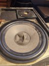
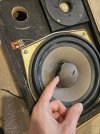
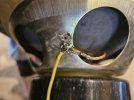
Okay so I decided to test the speaker again after the test and for some reason the tweeter is working again. I don;t know why. All I did was desolder the caps, tested them and resoldered them. The only thing that changed is that I reattached the yellow cable to the frame of the sub cone how it was before the shipping (I soldered it next to the whole where it was attached before because I wasn't sure it would get a good contact there). Maybe that made the difference? I will attach a picture. Still when I compared the two speakers the one where the tweeter was out doesnt sound as full. But it seems like bass (and maybe some mids) is missing not highs. The cones also got squished during the transit but the speaker that works better has a much more damaged cone (Its the one where the done is almost coming off, the one where it is just squished is the one where the tweeter was out.)

To summarize: Now both speakers are put together exactly the same. The only difference is the extent to which the sub cones are broken and the fact that I reattached the yellow cable different than it was before. (of course some of the components may still be broken on the crossover but aside from the caps I haven't tested anything yet.
 

Attachments

  • 20240205_114517.jpg
    20240205_114517.jpg
    105.4 KB · Views: 8
  • 20240205_115909.jpg
    20240205_115909.jpg
    139.5 KB · Views: 8
  • 20240205_120311.jpg
    20240205_120311.jpg
    84.1 KB · Views: 8
Back
Top Bottom