• The move to the new server is done. There are some software and database maintenance updates in process. This has us passing the hat around to help out. We appreciate any donations. Seriously, even a dollar helps. The payment page may be found here - https://www.audiokarma.org/support.html

Attempting to fix my dads RFT k13ProfiL

waxdaddy

New Member
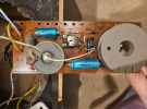
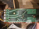
Trying to fix this speaker. Both drivers are working (tested them by holding the audio cable from my receiver directly to the contacts on the drivers) so i think there is a short on the pcb board. I know very little about electronics so it's hard for me to follow the path of current. I tried testing all the components using a continuity meter and most of them seem to be fine. Theres a bunch of them in the middle with the frolyt 100/25, the two 4 striped resistors and the brown one next to where it says VD1 that do not produce the sound.

Im sure i didnt do a very good job explaining so please ask questions to clarify! I just dont know enough about electronics to be any more coherent.

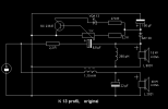
Adding pictures of the pcb and a circuit diagram found online. Blue/white is the tweeter, brown/yellow is the sub and white/brown (thin wires) is an LED.
 

Attachments

  • Screenshot 2024-02-04 084417.png
    Screenshot 2024-02-04 084417.png
    994 KB · Views: 10
  • Screenshot 2024-02-04 084432.png
    Screenshot 2024-02-04 084432.png
    962.5 KB · Views: 10
  • Screenshot 2024-02-04 150042.png
    Screenshot 2024-02-04 150042.png
    7.4 KB · Views: 11
Register to hide this ad
There is some info on these speakers under the Speakers forum here on AK.
  • Problem is likely located on the board, then, given we know that your receiver and both drivers are working. However, it's probably not "a short on the PCB board" (the pics do not show anything touching or messy soldering). It's more likely a bad part (component) like a capacitor which typically fail over the years.
  • I admit I am not familiar with these speakers but the PCB is a "crossover" to split the music signal into lows for the woofer/mid and highs for the tweeter. Also have an LED running off the board but IDK its purpose. A basic crossover consists of coils (two larger round forms) and 6.8uF and 22uF capacitors, but yours appears to have some kind of adjustment circuit along the top of the board in your pic, with a transistor, trimmer resistor, resistors, rectifier, and LED according to your schematic.
  • Checking for continuity: You should first check the capacitors (the blue cylindrical parts) using a capacitance test meter to see if good/within range. A capacitor's value is given in microfarads uF and max working voltage, and is usually printed on the part. Your schematic diagram shows 6.8uF, 22uF, and 100uF at 40 volts. Black part looks like the rectifier.
  • You say you have little electronics experience but that's OK since you're willing to learn, and that you checked for continuity which means you have a meter or test light. To check the caps you'll need an capacitance meter as well.
  • Hopefully it's a bad cap which is easily replaced. If it's not then you have to check the components at the top part of the schematic.
 
Last edited:
There is some info on these speakers under the Speakers forum here on AK.
  • Problem is likely located on the board, then, given we know that your receiver and both drivers are working. However, it's probably not "a short on the PCB board" (the pics do not show anything touching or messy soldering). It's more likely a bad part (component) like a capacitor which typically fail over the years.
  • I admit I am not familiar with these speakers but the PCB is a "crossover" to split the music signal into lows for the woofer/mid and highs for the tweeter. Also have an LED running off the board but IDK its purpose. A basic crossover consists of coils (two larger round forms) and 6.8uF and 22uF capacitors, but yours appears to have some kind of adjustment circuit along the top of the board in your pic, with a transistor, trimmer resistor, resistors, rectifier, and LED according to your schematic.
  • Checking for continuity: You should first check the capacitors (the blue cylindrical parts) using a capacitance test meter to see if good/within range. A capacitor's value is given in microfarads uF and max working voltage, and is usually printed on the part. Your schematic diagram shows 6.8uF, 22uF, and 100uF at 40 volts. Black part looks like the rectifier.
  • You say you have little electronics experience but that's OK since you're willing to learn, and that you checked for continuity which means you have a meter or test light. To check the caps you'll need an capacitance meter as well.
  • Hopefully it's a bad cap which is easily replaced. If it's not then you have to check the components at the top part of the schematic.
Hi, Thanks for your reply. The other post is also by me. I was trying to get a response fast so wanted to post in multiple places!

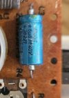
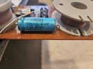
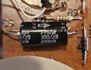
Can you help me identify which capacitor is which? Not sure which number on the parts refers to the Farads
 

Attachments

  • 20240205_100633.jpg
    20240205_100633.jpg
    58.1 KB · Views: 1
  • 20240205_100641.jpg
    20240205_100641.jpg
    76.8 KB · Views: 1
  • 20240205_100649.jpg
    20240205_100649.jpg
    73 KB · Views: 1
Last edited:
Tested the capacitors (two blue things and one black) for capacitance and they check out. Where do I go from here?
 
Hello ,I would desolder the diode (VD1) . Desoldering / lifting one side is enough to take the "led circuit "out of the filter .
Should it work without it , test at low volume ! ,you can then check the components within that circuit .
Hope this helps , regards F.
 
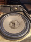
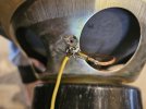
Okay so I decided to test the speaker again after the test and for some reason the tweeter is working again. I don;t know why. All I did was desolder the caps, tested them and resoldered them. The only thing that changed is that I reattached the yellow cable to the frame of the sub cone how it was before the shipping (I soldered it next to the whole where it was attached before because I wasn't sure it would get a good contact there). Maybe that made the difference? I will attach a picture. Still when I compared the two speakers the one where the tweeter was out doesnt sound as full. But it seems like bass (and maybe some mids) is missing not highs. The cones also got squished during the transit but the speaker that works better has a much more damaged cone (Its the one where the done is almost coming off, the one where it is just squished is the one where the tweeter was out.)

To summarize: Now both speakers are put together exactly the same. The only difference is the extent to which the sub cones are broken and the fact that I reattached the yellow cable different than it was before. (of course some of the components may still be broken on the crossover but aside from the caps I haven't tested anything yet.
 

Attachments

  • 20240205_114517.jpg
    20240205_114517.jpg
    105.4 KB · Views: 4
  • 20240205_115909.jpg
    20240205_115909.jpg
    139.5 KB · Views: 4
  • 20240205_120311.jpg
    20240205_120311.jpg
    84.1 KB · Views: 4
Back
Top Bottom