• The move to the new server is done. There are some software and database maintenance updates in process. This has us passing the hat around to help out. We appreciate any donations. Seriously, even a dollar helps. The payment page may be found here - https://www.audiokarma.org/support.html

Attention Project One Guru's

preacherJohn

Active Member
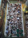
Hey guys, I have this absolutely, drop dead Project One Mark IVA receiver; looks GREAT and sounds good too, and it's 70s. Except for just a few scratchy pots it would pass for brand new. Someone has really taken care of it, or else put it on a pedestal with a glass cover. No blems whatsoever. It had one indicator light on the fm out, and I changed the dial lamps to warm LEDs to brighten it up as the dial glass is pretty dark. I may replace the caps on the power supply since it's so old, but I may just leave all others alone. The big 10000uf filter caps are still in spec also. So they'll stay the same. The only problem I have is the signal and tuner meters aren't working, and jiggling the wires didn't help. I can't find any schematic, service manuals, or notes on the fm section to trace this and the boards aren't marked either. So my question is for where should I start on these meters, or where do I go to start checking voltages, or what ever that feeds the signal to them? For those who know or worked on these PO's, is this a common problem? The fm sounds good, it seems pretty aligned, the dial is pretty much spot on the stations, the stereo light and multiplex works. If I knew which pots adjusted the meters, that would be a start. I'll post a few pics, and this thing is really clean too.
p1face.jpg
p1tuner.jpg
p1tuner2.jpg
p1pcb.jpg
 
Last edited:
Register to hide this ad
they look stuck. if so you can disassemble them and loosen the screw that the meters pivot on. it's tricky. you need steady hands. the screws are usually threadlocked heavily and if you try to remove without heat, you will trash the 'slot'

i use a soldering iron with a chisel tip. set the iron in the slot for a second, heat it up, then turn it left. blow on the meter to see if it moves freely, rinse and repeat. when it is moving freely, reassemble and hope that you didn't break it.

the front and rear of the meter housing is usually just scotch taped together. i've actually never seen meters that AREN'T taped together but they may exist.
 
they look stuck. if so you can disassemble them and loosen the screw that the meters pivot on. it's tricky. you need steady hands. the screws are usually threadlocked heavily and if you try to remove without heat, you will trash the 'slot'

i use a soldering iron with a chisel tip. set the iron in the slot for a second, heat it up, then turn it left. blow on the meter to see if it moves freely, rinse and repeat. when it is moving freely, reassemble and hope that you didn't break it.

the front and rear of the meter housing is usually just scotch taped together. i've actually never seen meters that AREN'T taped together but they may exist.
Wow, thanks I'll give that a shot. As good as this looks it may not have been used very much and not for a long time, so they very well may be stuck. I just run a signal gen and hooked it to a scope, and I got 57wpc out of it before clipping. I think it's rated for 55, but don't know for sure as there's not much info on it. I bet if I did a full restoration on it that it would hit close to 70. I'm really digging it right now hooked to a CD player playing some old Grand Funk Railroad on it. I'm going to have to check the bias on it before I go too much further, running it up to clipping got the heat sinks hot. Since I don't have a service manual I may check it across the emitter resistors and see where it's at.
 
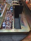
OK, moving along on this project Project One receiver I decided to check a few things before working with the meters. I recapped the power supply. 75% of the originals were grossly out of spec, with a few testing OK. I just replaced them all. I tested the transistors and they were alright. Wanting to check the bias and set it, I pulled this amp out and you wouldn't believe how easy it was, well thought out when designed. I figured that I could measure across the emitter resistors once I identified which was what. I checked the Output Qs, replaced the thermal paste, then traced their wires back to the resistors. I marked on the board where the emitter wire went, and then the base wire. The emitter wire ended up on the 5 watt resistors, and the base wires ended up on a 220 ohm resistor which tied to the other side of the 5 watters. See photo. So, should I hook my leads to the 220 ohm that it passes thru going to the 5 watter and then to the Emitter side of the other 5 watter to check the bias? I figured I'd set the bias to around say 20ma and check the heat on the heat sinks. Oh it does have an SA750 differential pair on those boards too. Usually I replace those with heat shrink to couple them together. As of now, they're not coupled, just facing one another and not touching. Since there's only a couple of caps on each board, I'm going to replace those also seeing how the PS was so out of spec. amp1 - second.jpg
amp2copy.jpg
amp3copy.jpg
amp4copy.jpg
 
Back
Top Bottom