• The move to the new server is done. There are some software and database maintenance updates in process. This has us passing the hat around to help out. We appreciate any donations. Seriously, even a dollar helps. The payment page may be found here - https://www.audiokarma.org/support.html

AU 20000 preliminary checks

richardpp

Well-Known Member
Hi, this is my first post here. Hope it finds you well!

I've recently acquired an AU 20000 and spent quite a bit of time browsing this forum, becoming familiar with some of the challenges, precautions, misfortunes and ultimate rewards involved in repairing this formidable amp. To paraphrase one of the contributing members, this may be a very tall mountain to climb, indeed. Help with any small step up would be much appreciated.

Here's what I have found so far:

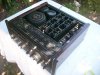
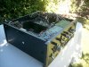
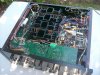
General condition is very good with no obvious evidence of repair work or damage. There is very little corrosion, if any at all, caused by glue. I'll put that down to the hot, dry Australia climate, in fact it was 41deg C (106 deg F ) just a few days ago!

Power on: soft start relay engages (protection light on) followed promptly by the speaker relay, (protection light off).

DC Offset Service Manual spec: 0V +/- 10mV
Actual reading: R/H, measured at over 100mV and still rising after 1/2 hour.
L/H, 1mV stable

Bias: measured as per AU 20000 Service Manual, specification: 35mV
Actual reading: R/H, 0.0 mV, L/H, 0.0mV


Thanks, and Happy New Year!

Richie.
 

Attachments

  • Sansui.au20000.3.JPG
    Sansui.au20000.3.JPG
    125 KB · Views: 60
  • Sansui.au20000.4.JPG
    Sansui.au20000.4.JPG
    117.6 KB · Views: 54
  • Sansui.au20000.5.JPG
    Sansui.au20000.5.JPG
    116 KB · Views: 60
Register to hide this ad
DC Offset Service Manual spec: 0V +/- 10mV
Actual reading: R/H, measured at over 100mV and still rising after 1/2 hour.
L/H, 1mV stable
Should be able to adjust it down to within spec.
Bias: measured as per AU 20000 Service Manual, specification: 35mV
Actual reading: R/H, 0.0 mV, L/H, 0.0mV
Check your rail voltages on the output transistor collectors +/- 68vdc
on both amplifier assemblies.
 
Last edited:
Hi and welcome to AK and the Sansui forum.

Great pick up on the AU20000 :thmbsp:, one of those have been on my wish list for quite a while.

Those Bias measurements don't sound promising, and neither does the DC offset drift.

Whereabouts in Aus are you?

Cheers

John
 
sounds like driver board problems. read the transistor testing sticky. remove and test the transistors on the driver boards. check the small el caps if you can.

You might as well get comfortable with removing the heat sink assys too. There are passthroughs that need to be pinned and resoldered on those pcbs in the middle.
 
@skippy124

Hi John,

Thanks for the welcome! I was fortunate to come across this amp at a garage sale in Adelaide. In fact, there were two of them, but the other has had parts removed, PT is missing :sigh:, as well as knobs, power switch, chassis parts etc., so that is for another day, though the DC offset and bias values of the 'better' amp are still a bit of a concern.

Look forward to staying in touch.

Cheers

Richie
 
sounds like driver board problems. read the transistor testing sticky. remove and test the transistors on the driver boards. check the small el caps if you can.

You might as well get comfortable with removing the heat sink assys too. There are passthroughs that need to be pinned and resoldered on those pcbs in the middle.

Okay, let's get started!
 
Hi DCinDC

I pulled the transistors from the R/H driver board, the side that had drifting DC offset, and checked them according to the forum 'sticky', using a DMM in diode test function. They all seem to be functioning normally. (L/H board transistors I checked 'in situ' by comparing values with the R/H)

The Emitter Resistor boards were certainly worth looking at. Pretty much every through connection showed some sign of cracking. Good advice!

I'm now thinking of putting the heatsink assy's back together and reinstalling them to see if there are any changes to my original readings, unless there are other suggestions at this point.

Also, the original V1212 diodes are still in place. I understand that these should be replaced with a series pair of 1N4148's, though I'm not sure if this is directly related to proper bias or DC offset function.

Thanks for your help.

Richie
 

Attachments

  • au-20000.JPG
    au-20000.JPG
    118.9 KB · Views: 45
  • heatsink assy.JPG
    heatsink assy.JPG
    100.8 KB · Views: 55
  • F 2487.JPG
    F 2487.JPG
    103.6 KB · Views: 62
Check from the end of the wire, all the way thru the emitter resistors to the emitter of the transistors.

I check these heat sink assys with a component checker thru the transistor junctions.

Good to see you have skills and will take direction! It is critical to your success.

I have found good driver transistors with back conduction. I replace the two driver transistors out of hand, without testing, now. Check the EL caps on those boards too.
 
I've checked the heatsink assys as thoroughly as I could before refitting them, but I'm unable to check the EL caps on the driver boards yet with anything more than a DMM.
@DCinDC, I'll keep in mind the driver transistors for when it's time to order parts, thanks.

After much hunting, I found a fault on the underside of the driver motherboard where a broken PCB trace prevented -65vdc supply to both driver boards. I had been mistaken previously in thinking that the supply to the driver boards was okay, relying on just the +/- 68v connections running from the protector board. This fault may well explain lack of bias current, common to both boards.

Hopeful of having solved the problem after repairing the broken trace, I was in the process of testing the amp when it began to lose voltage and the dim-bulb tester - which I made dutifully for the occasion - went bright. I suspect some weak transistors could no longer hold the soft-start relay in. (The relay had been giving a few tell-tale signs.)

So, there is still work to do, but for a moment there ...

Richie
 
Last edited:
Preliminary checks over!

The amp is back in service and I get to hear it for the first time. It 's connected to a pair of Rogers LS7 speakers.

The dim-bulb tester was upsetting the soft start, without it power on was normal. Left and right DC offset voltage stabilized and adjusted to spec. Bias current in left channel adjusted to spec. Right channel was problematic, but was able to substitute driver board and remedy.

Thanks to all who read these posts, especially DCinDC for advice on the driver boards and encouraging me to remove the heatsink assys.

Richie
 
Hello,
I realize this post started 2013, but, I have a question, so I’m throwing it out here, see if I get any bites!
Well into a AU20K, I am waay ahead of myself here,but, one concern I have after referencing this post is when the dim bulb test comes into Play. Do I need to circumvent the soft start relay To test at safe voltage?
And, if that is necessary, where/how is this done? :eek:
 
AURES.JPG Thanks Richard, As has been the case all along, I am seeing values differing from service manual/ other au20k’s. Circa:1975 probably explains alot!
 
Hi Joe, I found the schematic and parts list for the protector board to be accurate enough, apart from a few minor discrepancies. Those 10W resistors are obviously incorrect and should be 3.9 Ohm 7W.
 
Richard, you are right on the mark! It’s baffling?!, this is my first project of this complexity. Am seeing differences all over. Keeping a log of the outstanding ones.
Opening the case, noticed a sticker on the two 22k/80v EC’s,”1990”. It’s almost impossible to discern factory changes from past owners changes. This sansui did work, and sound like it should, I got married, couple kids, yada, yada. I stored it for 15+ years, fired it up once, both channels good, but electrolytic caps had clearly Degraded sound quality.
 
Back
Top Bottom