Hello,
In 2013 I bought a Sansui AU-555A.
Since then it had been working fine, at least for my expectations, except for the phono but I did not use it.
A few months ago, after reading, I don't remember where, that after 50 years an amplifier with original electrolytic capacitors (EC) should be considered a fire hazard, I decided as a first step to replace these capacitors on the phono (F-1267) board which had electrolyte (presumably) stains. And it actually fixed it.
More recently, one channel completely died so I decided it was time to replace all the remaining EC. I found a very detailed post on this forum from Leestereo about restoration and upgrade of an AU-555A but I chose to stay as close to the original as possible, at least for the moment.
The main (F-1266) board had also a lot of stains, so after de-soldering all the EC, I tried to clean the board with alcohol (EtOH/MeOH), cotton buds and a toothbrush. But finally I dipped the board in alcohol just up to the board surface for 24 hours in order to dissolve the dirt. The bath was completely yellow after that bath so I finally rinsed and dried the board.
By the way, 4 resistances that I measured too low when mounted, but at the correct value when de-soldered, were also replaced.
Then I soldered the new EC, double-checked everything and reassembled the system.
I bought a 8.2 Ohm/50 W resistance (manual recommends 8 or 16 Ohm/50 W) from a local store to load the system while doing the adjustments. The seller told me to be careful and not use it for too long because it is supposedly inductive and could re-inject a voltage inside the amp. I did not really get that, but I got that it gets freaking hot when pushing the volume knob quite high.
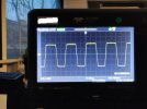
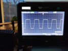
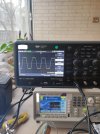
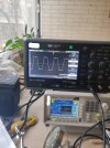
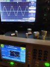
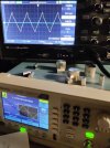
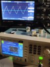
Then I followed the instructions, feeding a +/- 205 mV (manual recommends > 200 mV) 1 kHz sinusoid in the left Aux input and measuring the output wave on the left A channel with the load in place. For both right and left channels, I obtain a nice looking sinusoid. If I play with the corresponding adjustable resistance, I can make appear and disappear clipping but only on the upper part of the sinusoid, never at the bottom. The same applies at low or high volume. The same also applies if I bypass the pre-amp board (F-1272) by feeding directly to the main amp. after disconnecting the bridges.
Since it is the first time I am doing that, I am not sure if the clipping behavior is correct or not. At least I reckon I cannot achieve what is recommended by the manual, namely adjusting the resistance in order to get a symmetrical clipping at both the lower and upper part of the sinusoid. I don't know if adjustable resistances age well, so in case, I also bought replacement ones that I could use.
On the schematics that I have, some voltages are indicated, so I plan to start measuring these to provide more clues. However, I was wondering if I need to perform these measurements while the amp is loaded and if so, at what volume etc.
If my description rings some bells, I would really appreciate recommendations and comments.
Thank you very much for taking time to read this.
In 2013 I bought a Sansui AU-555A.
Since then it had been working fine, at least for my expectations, except for the phono but I did not use it.
A few months ago, after reading, I don't remember where, that after 50 years an amplifier with original electrolytic capacitors (EC) should be considered a fire hazard, I decided as a first step to replace these capacitors on the phono (F-1267) board which had electrolyte (presumably) stains. And it actually fixed it.
More recently, one channel completely died so I decided it was time to replace all the remaining EC. I found a very detailed post on this forum from Leestereo about restoration and upgrade of an AU-555A but I chose to stay as close to the original as possible, at least for the moment.
The main (F-1266) board had also a lot of stains, so after de-soldering all the EC, I tried to clean the board with alcohol (EtOH/MeOH), cotton buds and a toothbrush. But finally I dipped the board in alcohol just up to the board surface for 24 hours in order to dissolve the dirt. The bath was completely yellow after that bath so I finally rinsed and dried the board.
By the way, 4 resistances that I measured too low when mounted, but at the correct value when de-soldered, were also replaced.
Then I soldered the new EC, double-checked everything and reassembled the system.
I bought a 8.2 Ohm/50 W resistance (manual recommends 8 or 16 Ohm/50 W) from a local store to load the system while doing the adjustments. The seller told me to be careful and not use it for too long because it is supposedly inductive and could re-inject a voltage inside the amp. I did not really get that, but I got that it gets freaking hot when pushing the volume knob quite high.
Then I followed the instructions, feeding a +/- 205 mV (manual recommends > 200 mV) 1 kHz sinusoid in the left Aux input and measuring the output wave on the left A channel with the load in place. For both right and left channels, I obtain a nice looking sinusoid. If I play with the corresponding adjustable resistance, I can make appear and disappear clipping but only on the upper part of the sinusoid, never at the bottom. The same applies at low or high volume. The same also applies if I bypass the pre-amp board (F-1272) by feeding directly to the main amp. after disconnecting the bridges.
Since it is the first time I am doing that, I am not sure if the clipping behavior is correct or not. At least I reckon I cannot achieve what is recommended by the manual, namely adjusting the resistance in order to get a symmetrical clipping at both the lower and upper part of the sinusoid. I don't know if adjustable resistances age well, so in case, I also bought replacement ones that I could use.
On the schematics that I have, some voltages are indicated, so I plan to start measuring these to provide more clues. However, I was wondering if I need to perform these measurements while the amp is loaded and if so, at what volume etc.
If my description rings some bells, I would really appreciate recommendations and comments.
Thank you very much for taking time to read this.