• The move to the new server is done. There are some software and database maintenance updates in process. This has us passing the hat around to help out. We appreciate any donations. Seriously, even a dollar helps. The payment page may be found here - https://www.audiokarma.org/support.html

au-9900 stuck in protection mode

Hi I looked for the screw but couldn't find it... can you specify where is it located?
Tried testing for connectivity with my tester but it didn' t help much in finding the prob.
I also noticed that the sound controls ( treble/ midrange/bass) are not responding even if i move them way down/up! or pressing the 8/4/2 khz or 600/300/150khz buttons made any difference in the sound... that made me think that maybe I am not using the right replacement for the infamous 2sa798 transistor....( they are present in the phono stage and the sound controls boards) what are you guys using to replace it?
Thank you
 
More:
On the AU-9900 and AU-11000 there is a screw behind the front panel (you have to remove the front panel to see it) that provides the ground path for part of the circuits in the amp. If it gets loose it causes all kinds of weird problems. Rather than tightening the screw, I solder a ground braid to the chassis from the input selector board. If you turn the unit upside down, with the front panel facing you, it's the board on the left side front. As I recall, the ground is connected to the housing of the switch on the right side of the board as you are looking at it in the position above. Scrape some plating off the chassis by the front panel and solder a braid from the board to the chassis.
 
Hello
I am using 2sa970 paired together. I tried with 2sa1015 on the F2570 board as well but no change. Ksa's are not available here...I found out that 2sa992 are quite simmilar to ksa992 but 2sa992 are old as well and are not available...
 
Regarding the ground... the board in question is the d-2569? From the connector housing there are about 6 wires that go to the f2570 board...pin 01,06,05,02,09,12 of F2570. Should I add one wire and ground it to the chassis?
 
Regarding the ground... the board in question is the d-2569? From the connector housing there are about 6 wires that go to the f2570 board...pin 01,06,05,02,09,12 of F2570. Should I add one wire and ground it to the chassis?
If you look at the board you will see a large ground plane. You scrape off some of the solder mask and solder a wire or copper braid to the ground plane and to the chassis. You could also solder to the metal cover of the switch instead of the board.
 
I am sorry but the switch you are mentioning is the selector switch for aux1&2 and phono1&2? or is the one for the tuner? I don`t see any "large pad"
Thanks
 
I am sorry but the switch you are mentioning is the selector switch for aux1&2 and phono1&2? or is the one for the tuner? I don`t see any "large pad"
Thanks
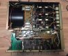
I can't find any photos of the bottom side on the internet to use as examples. Take a high resolution photo of the bottom with the controls facing you, make sure it's in focus, and post it here. I'll mark it to show where to solder the wire.
 
The plate ("metal cover of the switch") Doc references (in post #26) should be on the left, covering some/most of the green circuit board (if my memory servers me correctly) - in your 'strip down' you seem to have removed it along with the left side* cover ( *as shown in this view).
 
Last edited:
I had to remove it to be able to gain access to the back of the connectors board, to check for loose wires that might be stoping the phono inputs from working
 
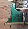
It's not really a high res photo so I can't see the switch pins and traces clearly but I believe I found the ground trace. If it's correct, the 4 mounting pins of the switch housing connect to this trace. Scrape the solder mask off the trace, and solder a wire from there to the chassis at any convenient point nearby, Scrape the plating off the chassis before you solder to it, or the solder won't stick.
 

Attachments

  • AU-9900 Switch Board Ground.jpg
    AU-9900 Switch Board Ground.jpg
    33.8 KB · Views: 40
The plate ("metal cover of the switch") Doc references (in post #26) should be on the left, covering some/most of the green circuit board (if my memory servers me correctly) - in your 'strip down' you seem to have removed it along with the left side* cover ( *as shown in this view).
No, the metal cover on the switch is on the other side of the board, the housing on the switch. It has 4 pins which go through the board and at least one of them connects to circuit ground.
The screw that completes the ground path is the one that secures that tuner switch to the inner front panel.
 
Well... soldered the wire in the ground path to the chassis... still no sound... I am really starting to hate this one!
The only thing left that I think is suspicious is that 2sa798 transistor... they are present in the sound controls boards as well.... I replaced them with paired 2sa970's ....
If I connect my ipod to aux, I do get sound but if move the bass & trebble controls sound stays the same... at least I don't notice any change in sound.
My only source to get these is fleabay but I really don't trust those guys or reinstall the old ones...
 
Last edited:
Bad transistors won't cause the tone controls to not work. Are you sure it isn't in Bypass mode? Check the switch.
 
Well....it`s official this amp is annoying me so much....is not the f2570 board...is not the grounding.....found out that resistors 1 & 2 (56k) and 3 & 4 ( 47k) in f2569 are about 10k lower than they should be... is that a a lot enough to make the phono inputs stop working? also found out that in the schematics that from pin 1 in f2570 should come out 32v but I`m getting only 9.4 (positive in the connector pin and minus in the chassis) and in pin02 should come out with -33v but getting only -11v...(again + in pin #2 and minus on chassis....)
 
Last edited:
F2568 power supply board check voltages pins 1 and 4 @+/-52vdc then measure both sides of zd01 and zd02 39v zeners.
 
ok, now pins 5 and 8 on that same board. Need to see +31/-32 volts, those voltages drive the pre amp section and need to be correct.
 
Back
Top Bottom