

You are using an out of date browser. It may not display this or other websites correctly.
You should upgrade or use an alternative browser.
You should upgrade or use an alternative browser.
AU-999 bias woes
- Thread starter xoaphexox
- Start date


stereofun
Super Member
When we set bias via emitter resistors, we plot the resistors nominal value into our little equation that tells us what the mV then should be. This is an assumption unless we measure their actual value.
In case of the 999, the emitter resistors are +/- 20% = 40% spread. Now worst case scenario based on a desired 30 mA setting, and a "calculated" 15mV across the resistors could make the actual bias we get swing from 25 mA to 37.5 mA - hardly anything that would burn a hole in the ground, yet on a percentage level quite a bit.
When the manual calls for measuring the actual current draw across the fuses, is that more accurate because the emitter variances inherently reflects, and then are balanced out when we adjust ?
I ask because whenever I have retested the emitter procedure against the service manuals current draw procedure there is usually a noticeable difference making one question whether to just follow the manual assuming Sansui could as well have asked us to probe resistors ?
I personally favor the emitter procedure, but I am curious to hear if anyone measures actual resistor value first and also some thoughts on why Sansui would ask us to measure current on the fuses.
In case of the 999, the emitter resistors are +/- 20% = 40% spread. Now worst case scenario based on a desired 30 mA setting, and a "calculated" 15mV across the resistors could make the actual bias we get swing from 25 mA to 37.5 mA - hardly anything that would burn a hole in the ground, yet on a percentage level quite a bit.
When the manual calls for measuring the actual current draw across the fuses, is that more accurate because the emitter variances inherently reflects, and then are balanced out when we adjust ?
I ask because whenever I have retested the emitter procedure against the service manuals current draw procedure there is usually a noticeable difference making one question whether to just follow the manual assuming Sansui could as well have asked us to probe resistors ?
I personally favor the emitter procedure, but I am curious to hear if anyone measures actual resistor value first and also some thoughts on why Sansui would ask us to measure current on the fuses.
Last edited:

I personally favor the emitter procedure, but I am curious to hear if anyone measures actual resistor value first and also some thoughts on why Sansui would ask us to measure current on the fuses.
I also like the across the emitter resistor method, and have tried the 'in line with fuse' method. I can only guess that Sansui thought the in line measurement of current was a direct reading that required no Ohms Law conversion, and as you say less dependance on the value of a resistor. I haven't measured emitter resistors with respect to Bias current adjustment, other than to confirm they are as approximately equal as I can resolve with my multimeter. I did once make a low Ohms measuring circuit 'add on' for an ordinary multimeter with a 3 terminal voltage regulator and a few other components, it worked well (better than I thought it would) but wasn't precision calibrated, so could only make comparative readings.
Note also that with some Sansui models bias current setting using the 'in line method' also measures the final driver stage current as well, just for a bit of extra spice when converting to the 'across the emitter resistor method'.

Last edited:

petehall347
the brandy coffee man
you just beat me to the extra spice bit .. i go with the manual first then measure over emitter resistors just to see .I also like the across the emitter resistor method, and have tried the 'in line with fuse' method. I can only guess that Sansui thought the in line measurement of current was a direct reading that required no Ohms Law conversion, and as you say no dependance on the value of a resistor. I haven't measured emitter resistors with respect to Bias current adjustment, other than to confirm they are as approximately equal as I can resolve with my multimeter. I did once make a low Ohms measuring circuit 'add on' for an ordinary multimeter with a 3 terminal voltage regulator and a few other components, it worked well (better than I thought it would) but wasn't precision calibrated, so could only make comparative readings.
Note also that with some Sansui models bias current setting using the 'in line method' also measures the final driver stage current as well, just for a bit of extra spice when converting to the 'across the emitter resistor method'.
suppose correct way is set to factory then tweak using a distortion analyser if you happen to have one lying around

ConradH
Lunatic Member
It does pay to measure emitter resistors. I once had an amp that was giving me fits, though I can't remember just why. It was THD or offset or asymmetrical clipping. Anyway, I finally found that one emitter resistor had gone high. Not by a huge amount, maybe from 0.22 ohms up to 0.6 ohms or so. It was close enough that I didn't notice it with a quick DVM check, figuring they'd do something more dramatic and I didn't have to be fussy. Wrong again!
Just a word of caution regarding translating the fuse current value to what is measured across emitter resistors (I have a mentioned this elsewhere).
For example -
Just had a 555A on the bench. The "Main Amp Current Adjustment" calls for 20ma as measured at the protection fuses in the supply to each channel. Now, if this method is used, you get the following readings across the 0.5 ohm emitter resistors in each channel -
High side emitter resistors (R845, R846) 7.5mv = 15ma current in the high side output transistor
Low side emitter resistors (R843, R844) 5.6mv = 11.2ma current in the low side output transistor
So if the current is set via measuring the high side emitter resistors, the resultant main amp current would be approx 25ma, and if set measuring the low side emitter resistors the resultant main amp current would be approaching 36ma - i.e. approaching double of the required main amp current. If one channel was set using the low side resistor, and the other side using the high side, then there would be a significant mismatch.
The difference may be more or less in the 999, when I get the chance I'll get my 999 on the bench and see what the differences there are between the setting the current via the fuse measurement method, and the resultant measurement across each of the 4 emitter resistors.
Cheers
John
For example -
Just had a 555A on the bench. The "Main Amp Current Adjustment" calls for 20ma as measured at the protection fuses in the supply to each channel. Now, if this method is used, you get the following readings across the 0.5 ohm emitter resistors in each channel -
High side emitter resistors (R845, R846) 7.5mv = 15ma current in the high side output transistor
Low side emitter resistors (R843, R844) 5.6mv = 11.2ma current in the low side output transistor
So if the current is set via measuring the high side emitter resistors, the resultant main amp current would be approx 25ma, and if set measuring the low side emitter resistors the resultant main amp current would be approaching 36ma - i.e. approaching double of the required main amp current. If one channel was set using the low side resistor, and the other side using the high side, then there would be a significant mismatch.
The difference may be more or less in the 999, when I get the chance I'll get my 999 on the bench and see what the differences there are between the setting the current via the fuse measurement method, and the resultant measurement across each of the 4 emitter resistors.
Cheers
John
Interesting John, may be a good reason to measure across both the high side and the low side resistors (with appropriate measurement voltage amendment), to help null-out this difference.
Just a thought, I wonder if you checked the resistance of the emitter resistors in this case?
Just a thought, I wonder if you checked the resistance of the emitter resistors in this case?

Trnsfmr
Well-Known Member
Interesting thread. We have tried lots of different way to measure bias. I don't like the resistor method because of the resistor tolerance. Sometimes there is a very narrow range to adjust the bias, like on the 5000 series. And who hasn't gotten a gigantor spark when trying to put the leads on the fuse holder?
Here's what we eventually came up with. We use old analog meters, and we got two of them, so we can look at both channels at once. Both of them are internally fused. But the main thing is the alligator clips. Look how they are insulated.
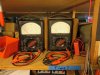
Now, LOL. I wish I could tell you where we got them, but I don't remember. I think Justin found them at a local store. In any case, they work well, with no more sparks when trying to grab the fuseholder.
Here's what we eventually came up with. We use old analog meters, and we got two of them, so we can look at both channels at once. Both of them are internally fused. But the main thing is the alligator clips. Look how they are insulated.
Now, LOL. I wish I could tell you where we got them, but I don't remember. I think Justin found them at a local store. In any case, they work well, with no more sparks when trying to grab the fuseholder.
petehall347
the brandy coffee man
if you were doing a few of these that suggest reading over the fuse holders you could use a broken fuse with wires soldered on to a nice little box with a fuse and a on off switch . first attach meter probes to fuse holder plus your lovely device . power up and let stabilise then flick the switch to connect meter instead of fuse . this way no sparks should occur . 

smurfer77
Super Member
In any case, they work well, with no more sparks when trying to grab the fuseholder.
Spark can and should be avoided by proper connection and power-on order.
Last edited:
Trnsfmr
Well-Known Member
Love those analog meters - especially having two side be side. C'mon Justin.....where did you find 'em...
He says he thinks he got them at Allelectronics.com . but he isn't sure. We buy a lot of stuff there, and the good stuff sells out pretty quick.
Trnsfmr
Well-Known Member
I agree with you. The problem always comes from not waiting long enough for the big power supply caps to discharge.Spark can and should be avoided by proper connection and power-on order.
smurfer77
Super Member
I agree with you. The problem always comes from not waiting long enough for the big power supply caps to discharge.
 We have all been there.
if you were doing a few of these that suggest reading over the fuse holders you could use a broken fuse with wires soldered on to a nice little box with a fuse and a on off switch . first attach meter probes to fuse holder plus your lovely device . power up and let stabilise then flick the switch to connect meter instead of fuse . this way no sparks should occur .
Hi Pete,
I have done something similar with blown fuses and i find this method easy to use and no sparks, no problems with meter fuses etc -

1 ohm resistors - mv measured = ma
used on an AU-7500

Cheers
John
petehall347
the brandy coffee man
i like that idea . saves on the potential expensive meter fuse blowing after forgetting to move the black probe back to volts and ohms .Hi Pete,
I have done something similar with blown fuses and i find this method easy to use and no sparks, no problems with meter fuses etc -
1 ohm resistors - mv measured = ma
used on an AU-7500
Cheers
John
Trnsfmr
Well-Known Member
So, I looked on Allelectronics site, and they don't have the exact set of insulated alligator clips, but they do have some almost the same, part # ALG-31.
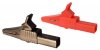
This is designed to go on the end of a banana plug test lead, their part # TL-125.
These clips look even better than the ones we have as they are completely insulated, all the way to the tip of the clip. I,m gonna get a couple pairs myself.
This is designed to go on the end of a banana plug test lead, their part # TL-125.
These clips look even better than the ones we have as they are completely insulated, all the way to the tip of the clip. I,m gonna get a couple pairs myself.

JRP225
Active Member
I've spent some time searching but haven't found what I'm looking for exactly. There's been a lot of discussion about bias adjustment/main current adjustment. Please excuse me for trying to spend less time searching (which I enjoy here) but I'm trying to get a quick parts list together. My question I'm eluding to is there anyone that could share part numbers for the multi-turn adjustment pots on the AU-999/ F-1159 board replacements for the single turn? I've seen a few pictures but can't seem to find a match. Digi-key or Mouser either way? I would be grateful.